
Interface circuit

Active Publication Date: 2007-10-18
RENESAS ELECTRONICS CORP
View PDF3 Cites 0 Cited by
  • Summary
  • Abstract
  • Description
  • Claims
  • Application Information

AI Technical Summary

Benefits of technology

[0015]The present invention enables a transmitting end to perform data output that is corrected in accordance with transmission status and a receiving end, thereby receiving data accurately. It only needs to add a function to output corrected data to the transmitting end only, thereby simplifying a system.

Problems solved by technology

However, the technique taught by Yamamoto needs to add a function for enabling accurate decision even with a changed pulse width to a receiving end, and it is necessary to add the function to each receiving device if there are a large number of receiving devices to receive data from a transmitting end, which causes an increase in system size and costs.
Further, because the technique corrects a received signal from the transmitting end by estimating a change, it sometimes fails to provide accurate decision depending on the degree of change.
Furthermore, because the period of High level at the receiving end is shortened in the open-drain output as described above, it hampers the high-speed transmission.
An increase in transmission speed causes failure to transmit a High-level signal to the receiving end, in which case it is difficult to make a correction at the receiving end.

Method used


Image

  • Interface circuit
  • Interface circuit
  • Interface circuit

Examples


Embodiment Construction

[0025]The invention will be now described herein with reference to illustrative embodiments. Those skilled in the art will recognize that many alternative embodiments can be accomplished using the teachings of the present invention and that the invention is not limited to the embodiments illustrated for explanatory purposed.

[0026]An exemplary embodiment of the present invention is described hereinafter in detail with reference to the drawings. In the below-described embodiment, the present invention is applied to a serial interface circuit with open-drain output. Although a serial interface circuit is used in the following description of the embodiment, the present invention may be also applied to a parallel output circuit. Further, although the circuit has an open-drain output in the following description of the embodiment, it may have an open-collector output.

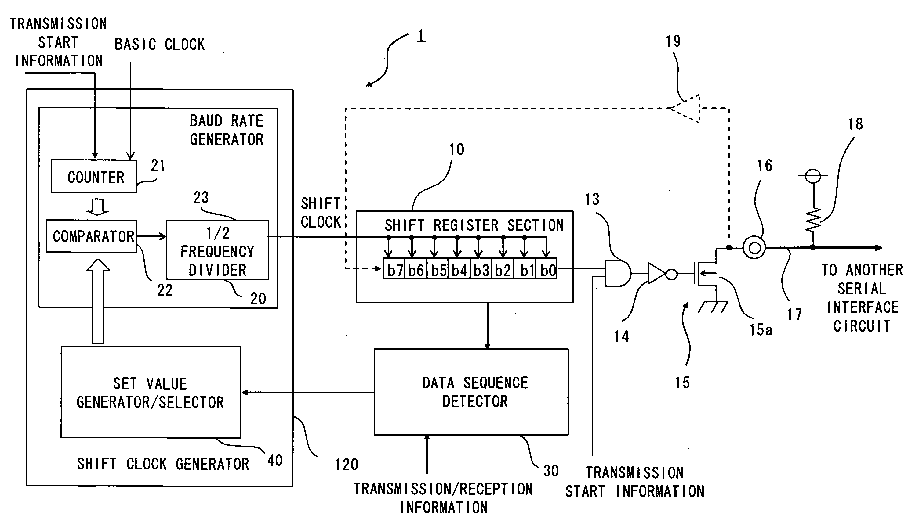
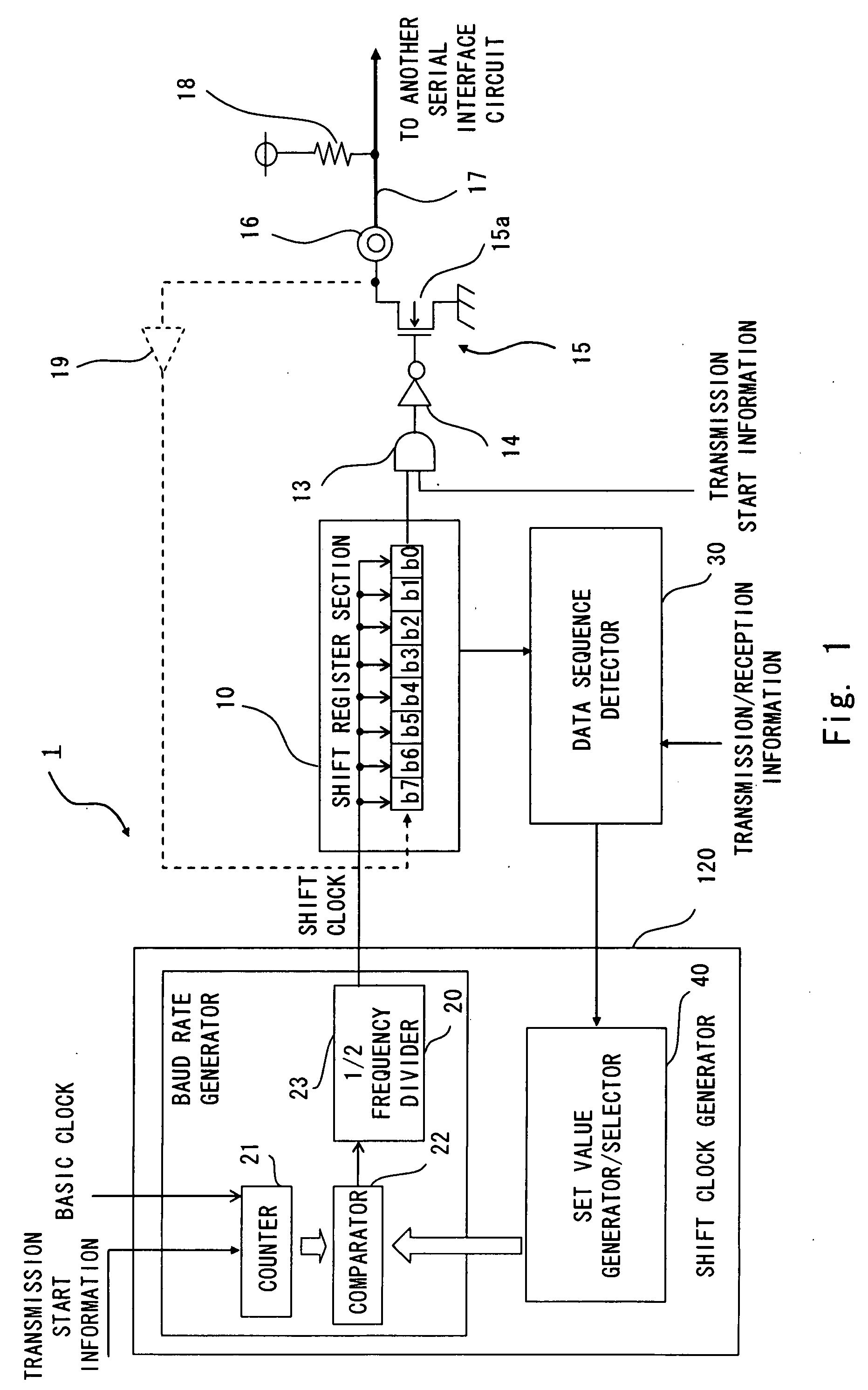
[0027]FIG. 1 is a view showing a serial interface circuit according to an embodiment of the present invention. The serial i...


PUM


Abstract

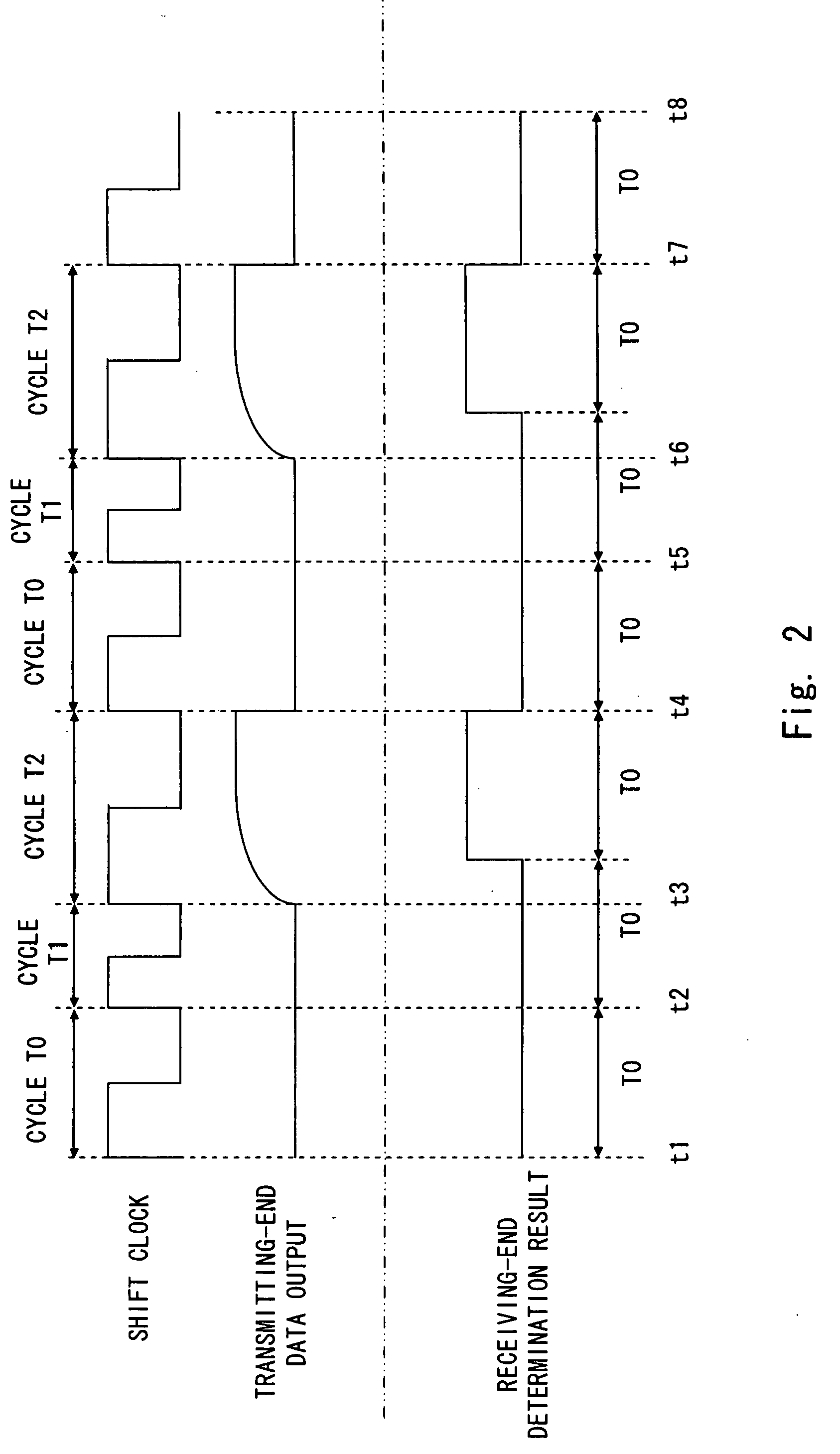
An interface circuit includes a detector to detect a particular pattern from a sequence of output data, a shift clock generator to change a cycle of a shift clock according to the detection result, a shift register section to change a data output width by the shift clock and output it as drive data, and an open-drain output section including an N-channel transistor driven by the drive data and a pull-up resistor. The detector detects a sequence where the current output data is “0” and the next output data is “1”, and the shift clock generator shortens and extends the cycles of the shift clock corresponding to “0” and “1”, respectively.

Description

BACKGROUND OF THE INVENTION[0001]1. Field of the Invention[0002]The present invention relates to an interface circuit including an open-drain or open-collector transistor.[0003]2. Description of Related Art[0004]FIG. 7 shows an example of a serial interface circuit according to a related art. The serial interface circuit 201 includes a shift register section 210 that receives data in parallel format through an internal bus and outputs the data in serial format to a receiving end, and a baud rate generator 220 that supplies a shift clock to the shift register section 210.[0005]During data transmission, the shift register section 210 receives data in parallel format from a controller (Central Processing Unit or CPU) or the like through an internal bus and outputs the data in serial format through an input / output terminal 216. During data reception, the shift register section 210 receives data in serial format from a receiving end through the input / output terminal 216 and an input buff...

Claims


Application Information

Patent Timeline
IPC IPC(8): H03M7/38
CPCG06F1/08
Inventor KUMAGAI, TOSHIYUKI
Owner RENESAS ELECTRONICS CORP
Learn More