Exercise device with elastic members and webbing

a technology of elastic members and exercise devices, which is applied in the direction of muscle exercise devices, gymnastic exercise, sport apparatus, etc., can solve the problems of not being able to pass through plugs, not being able to achieve a wide variety of exercises in various configurations, and not being able to allow for a change in resistance without replacement of its parts

Active Publication Date: 2014-01-23
LIFELINE PROD LLC
View PDF27 Cites 28 Cited by
  • Summary
  • Abstract
  • Description
  • Claims
  • Application Information

AI Technical Summary

Benefits of technology

[0005]Turning initially to FIGS. 1 and 2, an exemplary exercise device that illustrates preferred features of the invention is designated generally by the reference numeral 10. The exercise device 10, usable for various exercises in multiple configurations, includes a flat central webbing / band 100 with a first bridge 110 and a second bridge 120 on opposing ends 100A, 100B thereof. A first elastic member 130 extends from the first bridge 110, and a second elastic member 140 extends from the second bridge 120. The exercise device 10 may include a first loop 150 formed by the first bridge 110 and the first elastic member 130, and a second loop 160 formed by the second bridge 120 and the second elastic member 140. A first grip and a second grip may be a portion 170A, 170B of the first and second elastic members 130, 140, respectively, or portion 180A, 180B of a first handle 190 and a second handle 200, respectively. A user may push or pull on the first and second grips 170A, 170B / 180A, 180B with his or her hands, feet, wrists, ankles, elbows, knees, etc. to move the first and second grips 170A, 170B / 180A, 180B farther away from the first and second bridges 110, 120, stretching the first and second elastic members 130, 140 while engaging in various exercises. The dimensions and material of the central webbing 100 allows the user to more comfortably loop the exercise device 100 about his or her back. The first and second elastic members 130, 140 are preferably removably and replaceably securable to the first and second bridges 110, 120 to allow the user to change workout intensity by swapping in elastic members having different elasticities and / or lengths providing different resistances.
[0007]When the ends 100A, 100B of the central webbing 100 are pulled apart such that the central webbing 100 is effectively planar and taut, the first and second bridges 110, 120 are a separation distance 290 apart from each other. This separation distance 290 is preferably adjustable by allowing the relative position of the first and second bridges 110, 120 with respect to the central webbing 100 to be changed. To allow such adjustability, the second bridge 120 may include a second bridge passageway 300 through which the central webbing 100 may pass. A webbing securing mechanism 310 (such as a cam mechanism) that is biased to secure the second bridge 120 to the central webbing 100 may be incorporated into the second bridge 120. The webbing securing mechanism 310 may include a webbing release lever 320 that is movable between a grip state (as in FIG. 1) in which the central webbing 100 is restricted from passing through the second bridge passageway 300 by the webbing securing mechanism 310, and a release state (as in FIG. 2) in which the central webbing 100 is not restricted from passing through the second bridge passageway 300 by the webbing securing mechanism 310. The separation distance 290 between the first bridge 110 and the second bridge 120 may be adjusted when the webbing release lever 320 of the webbing securing mechanism 310 is in the release state. A webbing stop 330 may be incorporated at the webbing second end 100B (for example, by folding over a portion of the central webbing 100 and sewing it back onto itself) as a safety measure to restrict the second bridge 120 from sliding beyond the webbing second end 100B and entirely off the central webbing 100. A decrease in the separation distance 290 may increase a user's exertion during exercises by increasing the length to which the first and second elastic members 130, 140 are stretched during repeating exercise motions.
[0009]The exercise device 10 may include the first handle 190 and the second handle 200 with the first grip 180A and the second grip 180B, respectively. The first and second grips 180A, 180B of the first and second handles 190, 200 may include a first channel 480A and a second channel 480B formed therein for passage of the first and second elastic members 130, 140 therethrough, respectively. The first and second handles 190, 200 may optionally include first and second handle bases 490, 500 extending from the first and second grips 170A, 170B / 180A, 180B, respectively. Each of the first and second handle bases 490, 500 is preferably separated from the first and second grips 170A, 170B / 180A, 180B, respectively, to allow the fingers of a user's hand to pass therebetween. Such a configuration allows the user to insert four fingers between the grip and base of a handle and grasp the grip using his or her thumb and their fingers. This combination of grip and base allow the user to do push-ups more comfortably since the wrists are not as flexed.

Problems solved by technology

The elongated middle portions of the elastic cables are able to pass through the cable pockets but the plugs are not able to pass therethrough.
Traditional exercise devices with elastic cables (such as devices with a pair of handles bridged by an elastic cable), however, are not easily stabilized in various configurations to achieve a wide variety of exercises.
They also tend not to allow for a change in resistance without replacement of its parts (such as replacement of an elastic cable having a first elasticity / length with another elastic cable having a second elasticity / length).

Method used


Image

  • Exercise device with elastic members and webbing
  • Exercise device with elastic members and webbing
  • Exercise device with elastic members and webbing

Examples


Embodiment Construction

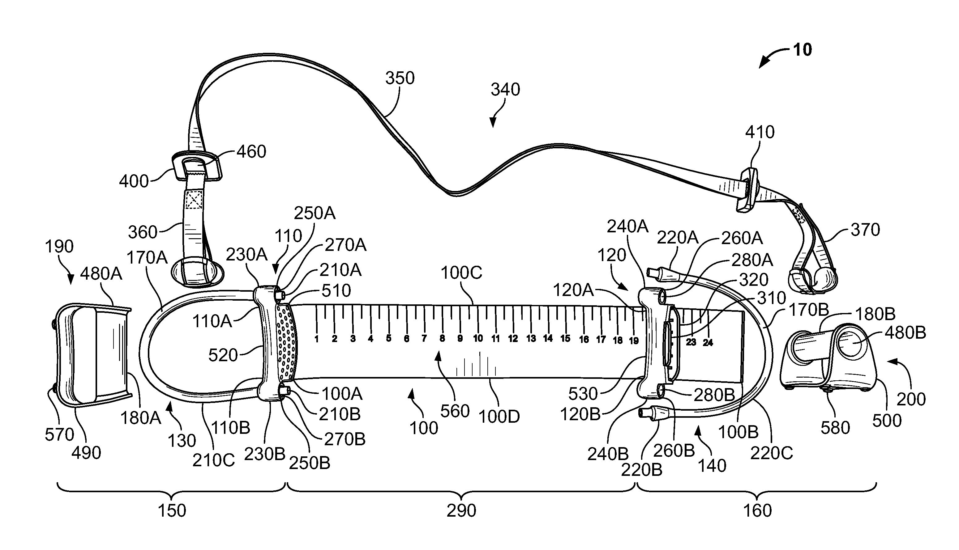
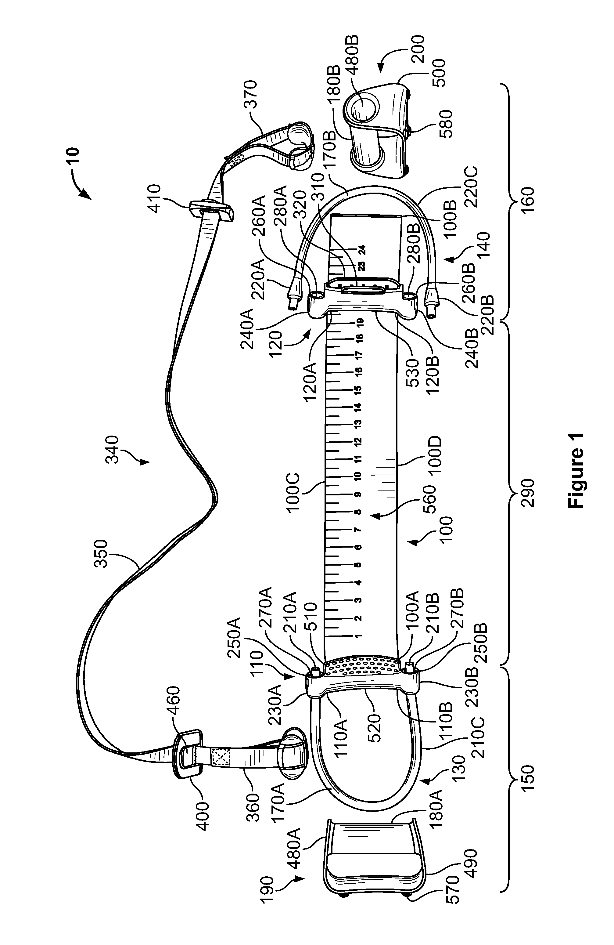
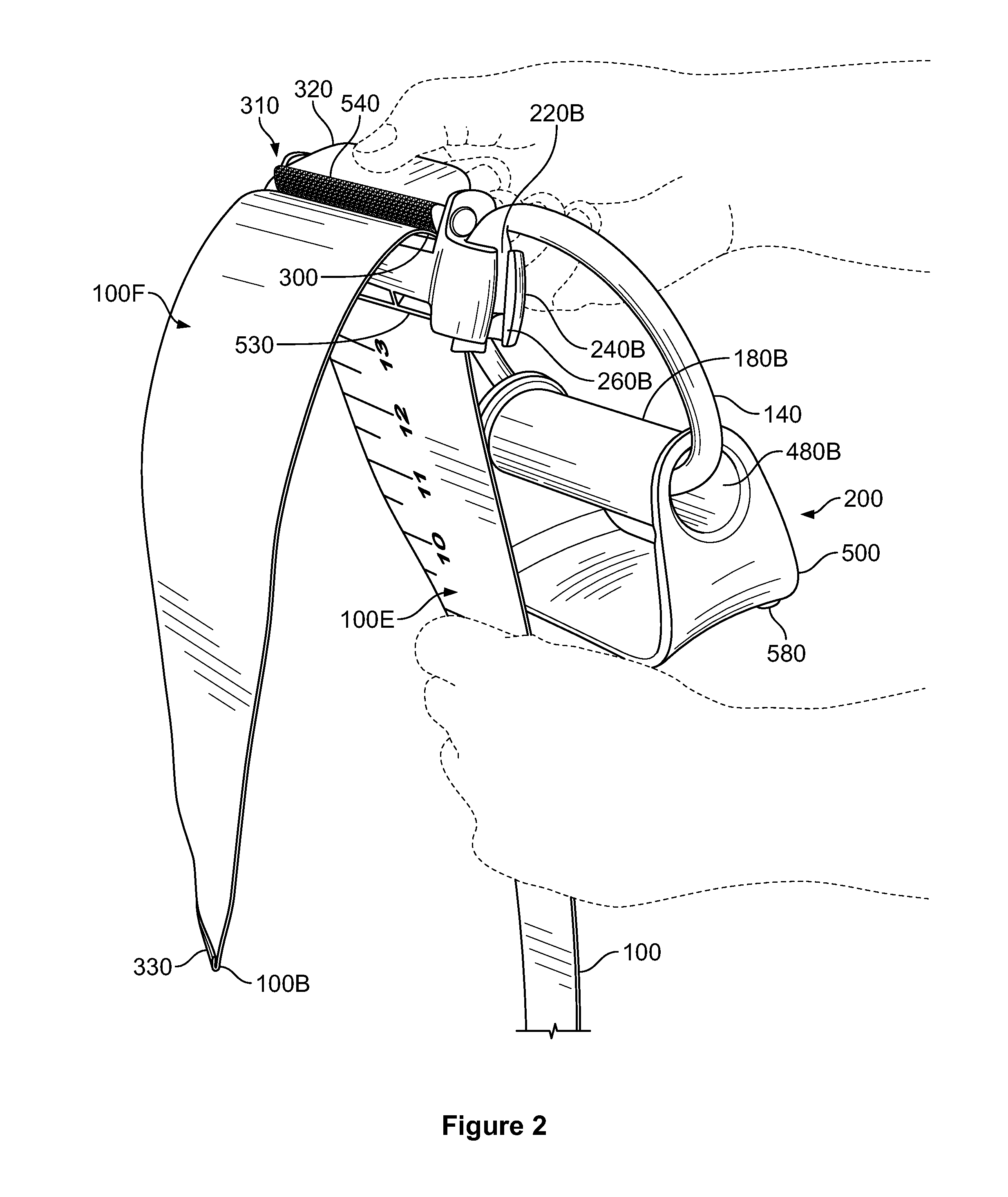
[0014]Returning to FIGS. 1 and 2, an exemplary exercise device 10 that illustrates preferred features of the invention is designated generally by the reference numeral 10. The flat central webbing 100 has a webbing length extending from a webbing first end 100A to a webbing second end 100B, a webbing width extending from a webbing first edge 100C to a webbing second edge 100D, and a webbing thickness extending from a webbing first face 100E to a webbing second face 100F (see also FIG. 2). In exemplary versions, the central webbing 100 length may be equal to or greater than eight inches, the webbing width may be equal to or greater than one inch, and the webbing thickness may be equal to or smaller than 0.25 inches. The version represented in FIGS. 1 and 2 includes a webbing length of about 24 inches, a webbing width of about four inches, and a webbing thickness of about 0.075 of an inch.

[0015]The central webbing 100 allows for a relatively large surface area of contact with the body...


PUM


Abstract

An exercise device for various exercises includes a pair of bridges on opposing ends of a relatively inelastic, flat central webbing / band / belt, with an elastic member extending from each bridge. The elastic members themselves may serve as grips (for hands, feet, ankles, arms, wrists, etc.), or separate grips (such as those of a handle) may be used. The elastic members include a pair of bulbs on opposing ends of a body, and may be secured to the bridges and handle grips via cradles (in which the bulbs may be lodged) and / or channels (through which the bodies may be passed). A user may push or pull on grips with hands or feet to stretch the elastic members while exercising. The elastic members are preferably exchangeable to allow the user to change workout intensity by swapping in elastic members having different elasticities / lengths that provide different resistances.

Description

CROSS-REFERENCE TO RELATED APPLICATIONS[0001]This application claims priority under 35 USC §119(e) to U.S. Provisional Patent Application 61 / 672,499 filed Jul. 17, 2012, the entirety of which is incorporated by reference herein.FIELD OF THE INVENTION[0002]This document concerns an invention relating generally to a versatile exercise device usable for various exercises in multiple configurations, and more specifically to an exercise device having stretchable elastic members extending from relatively inelastic central webbings.BACKGROUND OF THE INVENTION[0003]Elastic cables are able to resist stretching to varying degrees, and can be used in different configurations to simulate weights in various exercises. An elastic cable can be secured to exercise bar sections, handles, etc. to perform desired exercises. U.S. Pat. Nos. 6,923,750 and 6,497,641 to Hinds (incorporated by reference herein) show elastic cables with elongated middle portions and (male) plugs at opposing ends. Handles wit...

Claims


Application Information

Patent Timeline
Patent Type & Authority Applications(United States)
IPC IPC(8): A63B21/02
CPCA63B21/02A63B21/00185A63B21/0442A63B21/0552A63B21/0557A63B21/1645A63B2225/09A63B21/00043A63B21/00061A63B21/4035
Inventor HINDS, ROBERT S.POLINSKY, GLENN
Owner LIFELINE PROD LLC
Why Eureka
Try Eureka