Non-contact transformer system

Active Publication Date: 2014-01-30
PHIHONG TECH CO LTD
View PDF2 Cites 5 Cited by
  • Summary
  • Abstract
  • Description
  • Claims
  • Application Information

AI Technical Summary

Benefits of technology

[0012]The present invention has the following advantages: (a) the ability to be applied in the products with high power output; (b) the improved magnetic field conversion efficiency of the magnetic component; (c) the elongated contact distance between transmitting and receiving; (d) the primary side and secondary side components of the rear stage half bridge circuit can be switched at zero voltage or zero current to enhance the overall circuit efficiency; (e) when used in a lighting equipment, the requirement for connecting terminals between the lamp and the transformer can be eliminated to save

Problems solved by technology

The higher currents increase the energy lost in the distribution system, and require larger wires and other equipment.
Because of the costs of larger equipment and wasted energy, electrical utilities will usually

Method used


Image

  • Non-contact transformer system
  • Non-contact transformer system
  • Non-contact transformer system

Examples


Example

[0025]Preferred embodiments and aspects of the invention will be described to explain the scope, structures and procedures of the invention. In addition to the preferred embodiments of the specification, the present invention can be widely applied in other embodiments.

[0026]The invention provides a non-contact transformer system with a high power factor and power factor correction to improve the non-contact transforming efficiency.

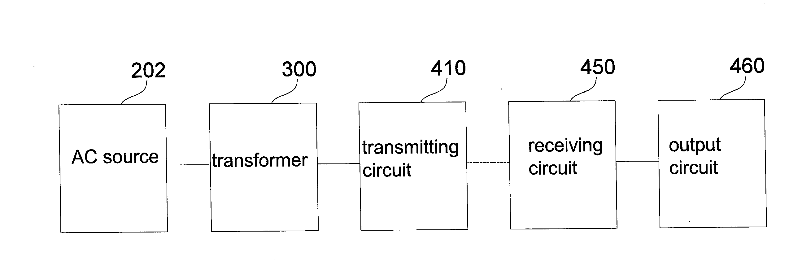
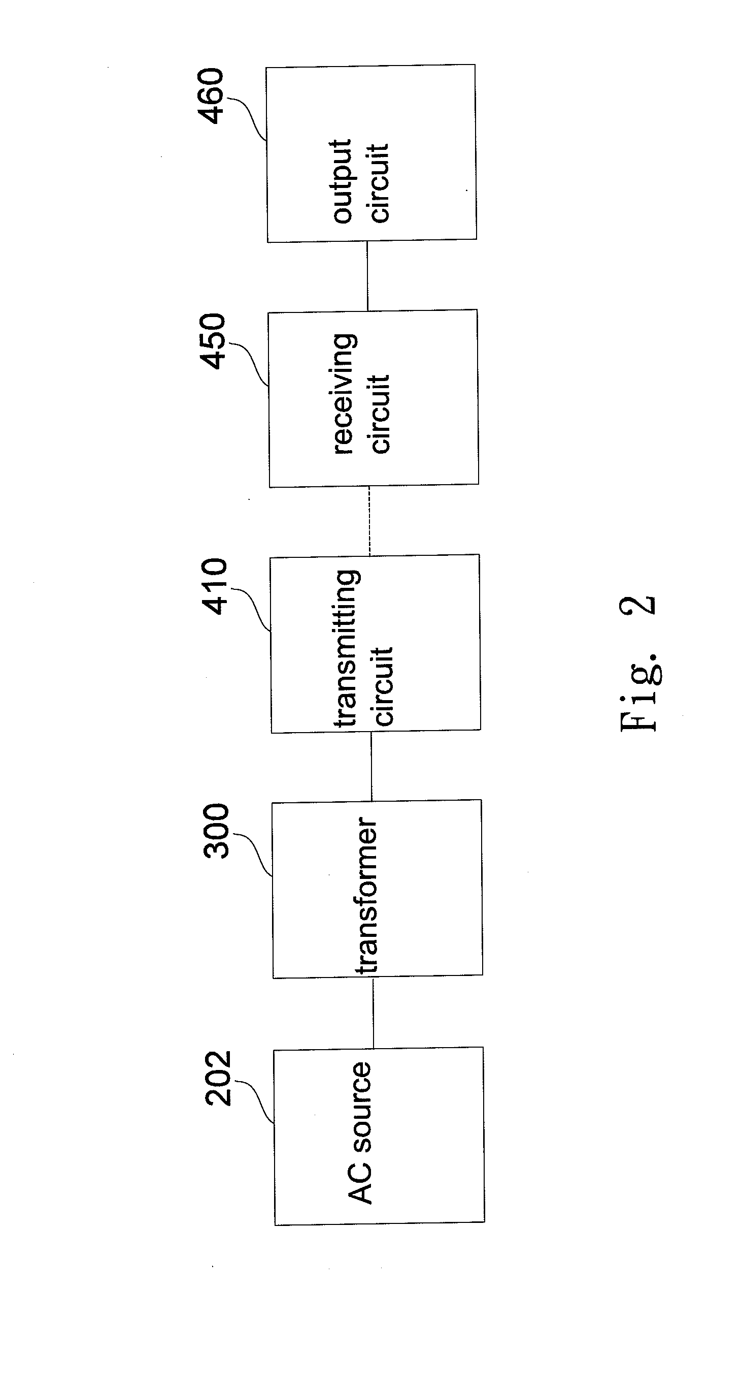
[0027]FIG. 2 shows a non-contact transformer system according to an embodiment of the invention, including: an alternating current source (202), a transformer (300), a transmitting circuit (410), a receiving circuit (450) an output circuit (460). The alternating current source (202) can be supply mains, and the output circuit (460) can be electric loadings, including chargers, lamps, etc. And, the non-contact interface exists between the transmitting circuit (410) and the receiving circuit (450) to replace wires.

[0028]When the invention is used in a lighti...


PUM


Abstract

A wireless transformer system comprises a primary side of AC/DC converter with power factor correction and a secondary side of a half bridge resonant DC/DC converter to power a device wirelessly.

Description

FIELD OF THE INVENTION[0001]The invention is relevant to a transformer system, especially a non-contact transformer system.DESCRIPTION OF THE PRIOR ART[0002]The power factor of an electrical power system is defined as the ratio of the real power flowing to the load to the apparent power in the circuit. An electrical power system with the higher power factor can save the energy lost in the distribution.[0003]In an electric power system, a load with a low power factor draws more current than a load with a high power factor for the same amount of useful power transferred. The higher currents increase the energy lost in the distribution system, and require larger wires and other equipment. Because of the costs of larger equipment and wasted energy, electrical utilities will usually charge a higher cost to industrial or commercial customers where there is a low power factor.[0004]Linear loads with low power factor (such as induction motors) can be corrected with a passive network of capa...

Claims


Application Information

Patent Timeline
IPC IPC(8): H01F38/14
CPCH01F38/14H02J50/12
Inventor CHEN, CHUN-CHENYU, PO- CHINGCHANG, WEI-CHUN
Owner PHIHONG TECH CO LTD
Why Eureka
Try Eureka