
Self-excited power conversion circuit for secondary side control output power

Active Publication Date: 2016-03-24
GIGALINK TECH HLDG LTD
View PDF2 Cites 3 Cited by
  • Summary
  • Abstract
  • Description
  • Claims
  • Application Information

AI Technical Summary

Benefits of technology

The present invention provides a self-excited power conversion circuit for secondary side control output power, which comprises an input module, a self-excited conversion module and an output module. The output module includes a comparator unit, a driver unit, and a modulator unit. The comparator unit detects and forms a detected value, which is compared with a reference value, and then outputs a drive signal to the driver unit to trigger the modulator unit to adjust a duty cycle of the input voltage outputted by the transistor. The invention achieves the effect of controlling the self-excited power conversion circuit to output a constant power directly from a secondary side, and overcomes the problem of the prior art that requires the installation of an additional feedback device for controlling the power factor from the primary side and causes a complicated circuit and a high cost.

Problems solved by technology

On the other hand, such structure is lack of a constant power control mechanism, so that the output power will increase with the input voltage, and thus giving rise of the problem of unable to maintain a stable illumination brightness and the issue of ageing quickly.
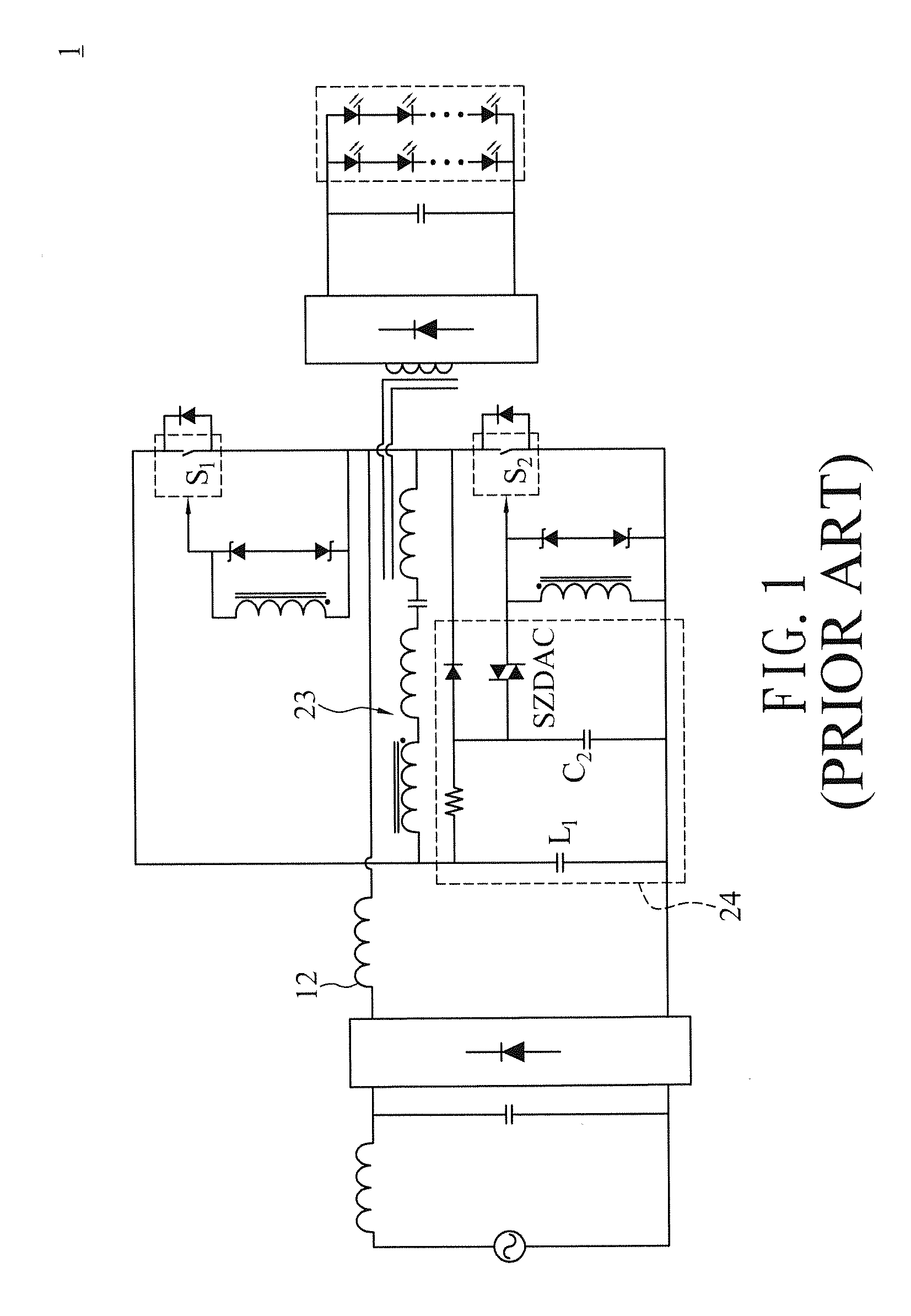
However, the quasi resonant half-bridge circuit 23 adopting the aforementioned method is installed in a primary side of the light emitting diode driver circuit 1, and thus resulting in an increase of the complexity of the circuit and a disadvantage of causing the overall structure of inductive impedances to have an electromagnetic interference issue easily.

Method used


Image

  • Self-excited power conversion circuit for secondary side control output power
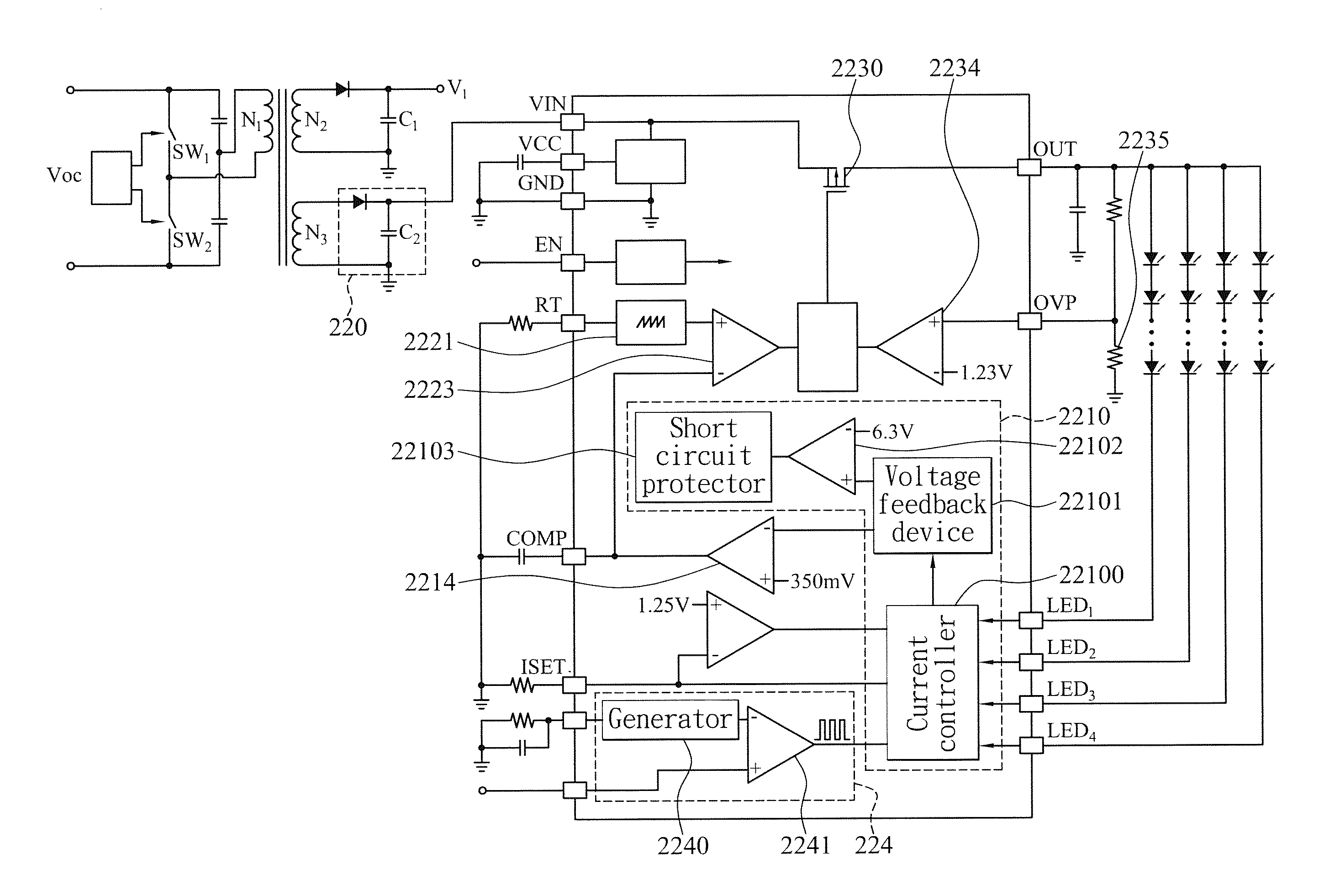
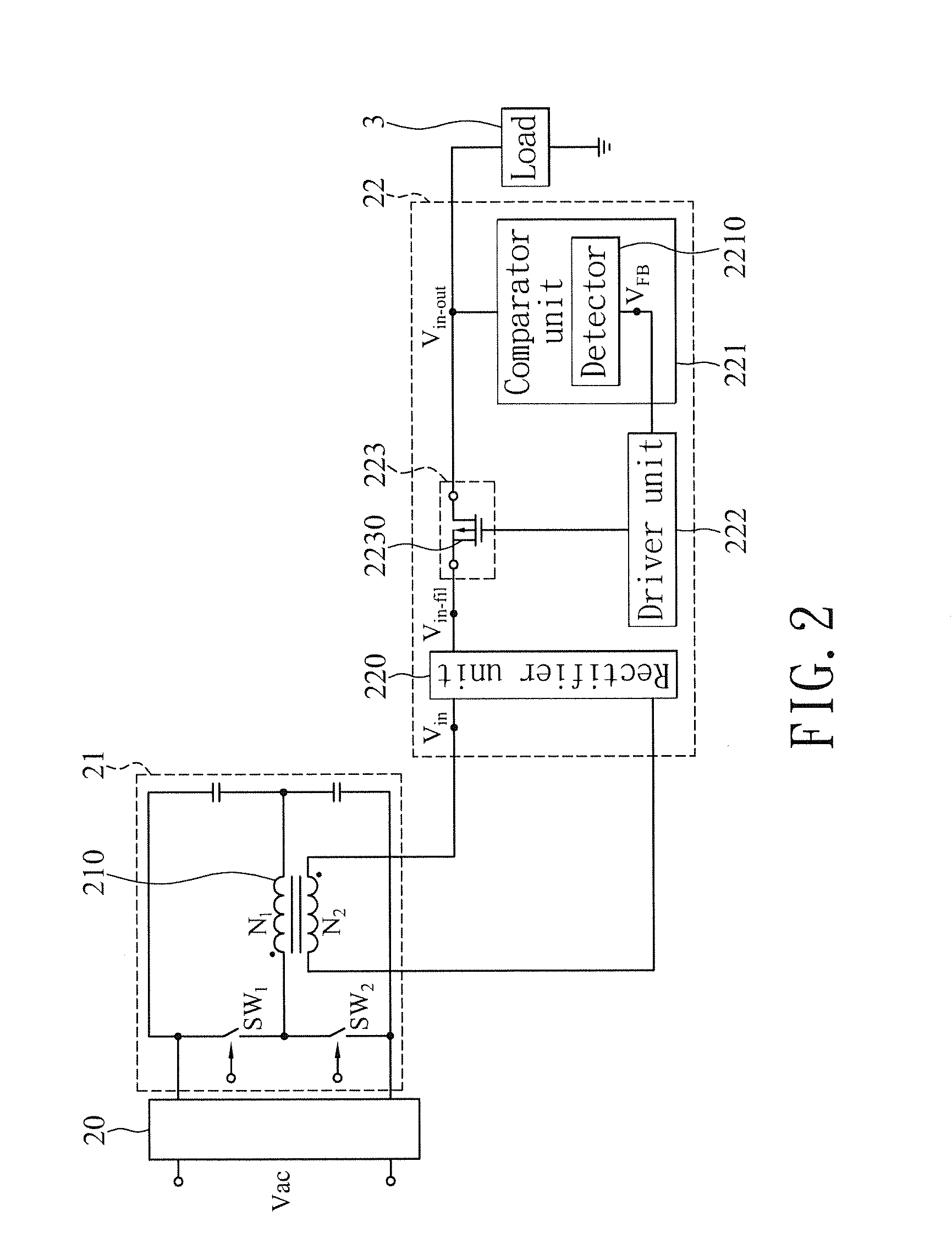
  • Self-excited power conversion circuit for secondary side control output power
  • Self-excited power conversion circuit for secondary side control output power

Examples


Embodiment Construction

[0023]The technical content of the present invention will become apparent with the detailed description of preferred embodiments and the illustration of related drawings as follows.

[0024]With reference to FIGS. 2 and 3 for a block diagram and a waveform diagram of a preferred embodiment of the present invention respectively, the self-excited power conversion circuit 2 capable of controlling the power output from a secondary side is applicable for an illumination device such as a lamp or a backlight module electrically coupled to at least one load 3, for providing a constant output power to assure the light emitting intensity and stability of the load 3 to improve the overall operating efficiency of the equipment. In other words, the self-excited power conversion circuit 2 can be used as a constant voltage source. The self-excited power conversion circuit 2 comprises an input module 20, a self-excited conversion module 21 and an output module 22, and the output module 22 is electrica...


PUM


Abstract

A self-excited power conversion circuit for secondary side control output power includes a comparator unit and a transistor installed directly in a secondary side output module, and the comparator unit is electrically coupled to at least one load, and the transistor is electrically coupled between to a conversion module of the circuit and the load. The comparator unit is provided for adjusting the duty cycle of the transistor after detecting the amount of energy outputted from the conversion module to the load from, so as to adjust the amount of energy actually received by the load to achieve a constant power effect.

Description

BACKGROUND OF THE INVENTION[0001]1. Field of the Invention[0002]The present invention relates to the technical field of a self-excited power conversion apparatus, and more particularly to a self-excited power conversion circuit for secondary side control output power capable of adjusting the duty cycle of the secondary power output automatically and directly without the need of feeding back to the primary side to achieve a constant output power effect, after a secondary side output voltage is detected by a secondary side control chip installed in a transformer.[0003]2. Description of the Related Art[0004]In general, a driver circuit is installed between a main circuit and a control circuit to drive the operation of an illumination device and convert the mains power to a power with an operating voltage and a current required for outputting a load, and an isolated circuit installed is installed between the main circuit and the load of the illumination device to provide the function of...

Claims


Application Information

Patent Timeline
IPC IPC(8): H02M3/335
CPCH02M3/33507H02M3/338H02M1/007
Inventor HSIAO, CHENG-POHUANG, CHUNG-HSINCHEN, KE-HORNGKUO, CHUN-CHIEHTU, SHIH-PINGCHIU, SHAO-WEI
Owner GIGALINK TECH HLDG LTD
Learn More