

Vehicle-use electric generator apparatus
- Summary
- Abstract
- Description
- Claims
- Application Information
AI Technical Summary
Benefits of technology
Problems solved by technology
Method used
Image

Examples
modified embodiment
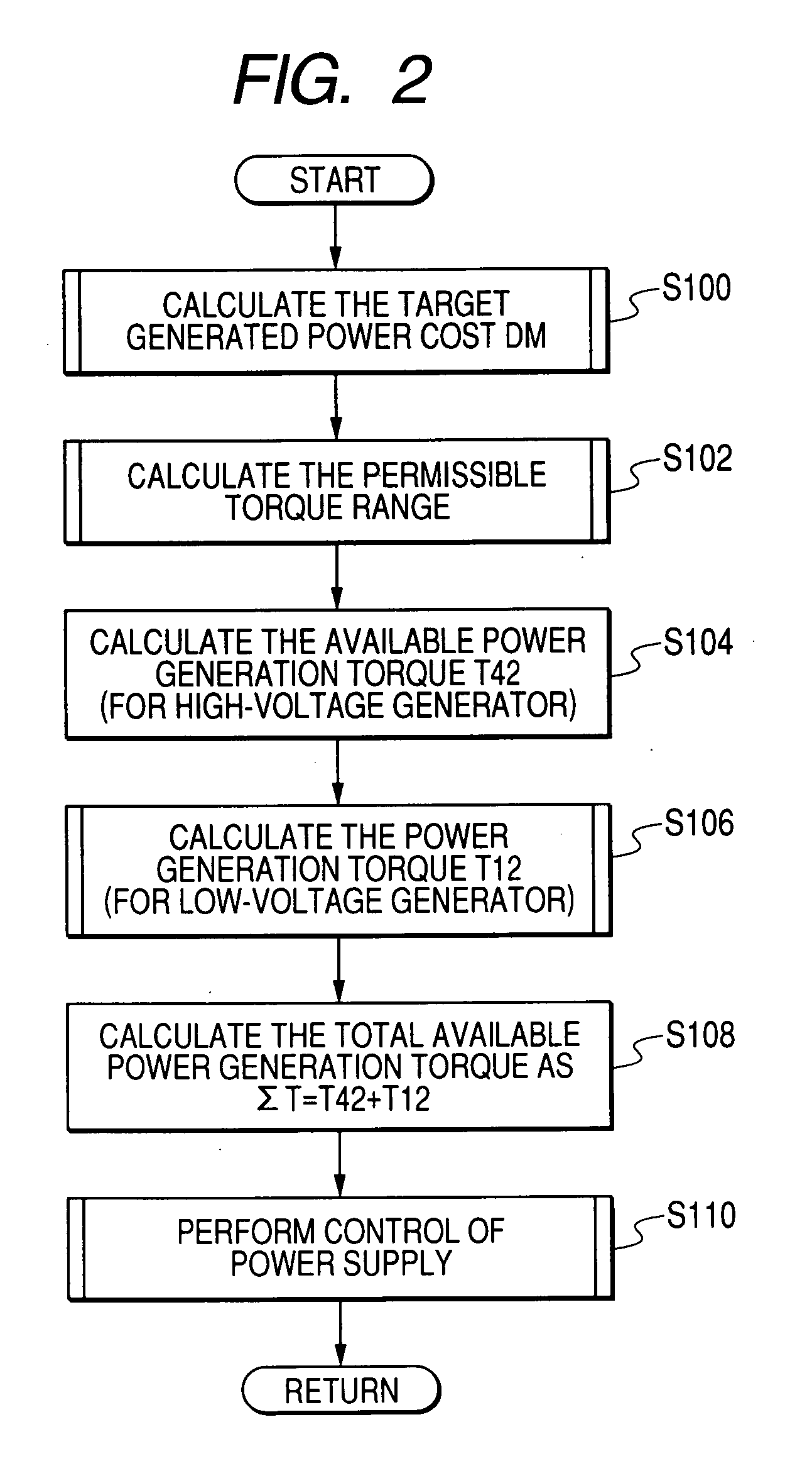
[0151] A modified embodiment will be described in the following. FIG. 12 is a flow diagram of the contents of step S110 of FIG. 2, for this modified embodiment. As shown, the control processing differs from that of the first embodiment described above with respect to the judgement made in step S1108 and the processing of step S1110 in FIG. 5 for the first embodiment, with these steps being respectively replaced by the steps S1109 and S1111 in FIG. 12. In other respects, the operation is identical to that of the above embodiment.
[0152] In this case, instead of the judgement of step S1108 described above, a decision is made in step S1109 as to whether:
[0153] (a) the sum of the zero-power torque value T0 and the total available power generation torque ΣT is greater than a minim-cost engine torque TX, which corresponds to the minimum electric power generation cost X (shown in FIG. 4) while also
[0154] (b) the sum of T0 and the power generation torque T12 is less than the minimum-cost ...
PUM
 Abstract
Description
Claims
Application Information