Mobile information terminal and operation state determination method

a mobile information terminal and operation state technology, applied in the field of mobile information terminals, can solve the problems of difficult for users to touch the icon or link displayed in the area of one-handed operation, the area of touch sensitive screen, and the inability of conventional mobile information terminals to perform screen display suited, etc., to achieve the effect of high accuracy

Inactive Publication Date: 2014-01-30
NTT DOCOMO INC
View PDF1 Cites 90 Cited by
  • Summary
  • Abstract
  • Description
  • Claims
  • Application Information

AI Technical Summary

Benefits of technology

[0012]The mobile information terminal according to the present invention can determine with high accuracy whether the user's operation state is one-handed operation or two-handed operation, regardless of variability in user's gripping features among individuals.

Problems solved by technology

Although the gripping states and operation states of the mobile information terminal vary as described above, conventional mobile information terminals cannot perform screen display suited to each gripping state and each operation state.
For example, if the user grips the terminal in the right (left) hand and attempts to operate the touch sensitive screen with the right (left) thumb (this operation method will be referred to as one-handed operation), some areas of the touch sensitive screen, such as the top right corner, the bottom left corner, the top left corner, and the bottom right corner, become difficult to reach for the right (left) thumb.
If an icon or link is displayed in those areas, it has been difficult for the user to touch the icon or link displayed in those areas while performing one-handed operation.
If the train jolts while the user is not holding on to the strap or rail, the user may fall down.
The same inconvenience will occur when the user attempts to operate the mobile information terminal with one hand while carrying in the other hand a load that cannot be carried on his or her back.

Method used


Image

  • Mobile information terminal and operation state determination method
  • Mobile information terminal and operation state determination method
  • Mobile information terminal and operation state determination method

Examples


first embodiment

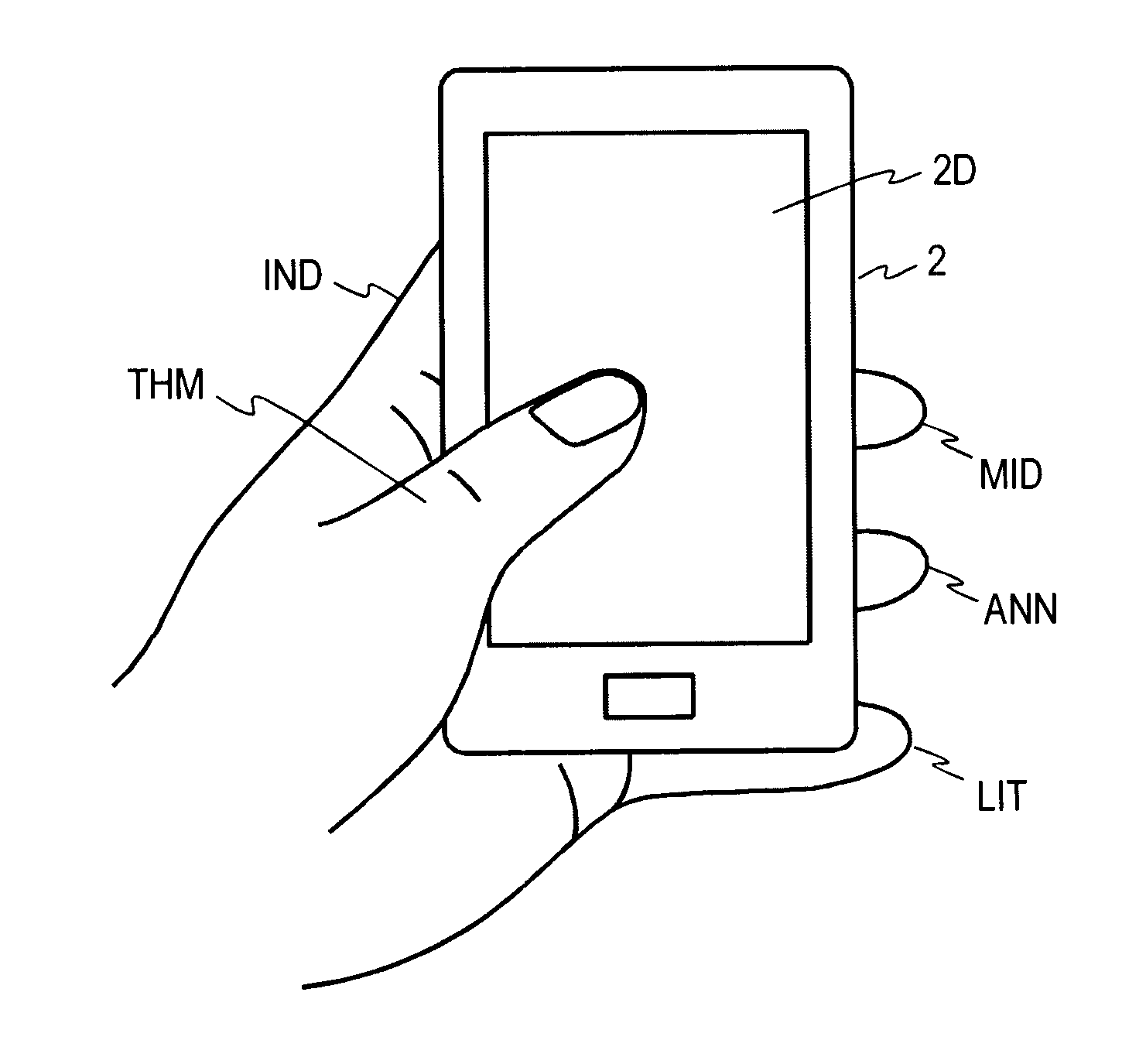
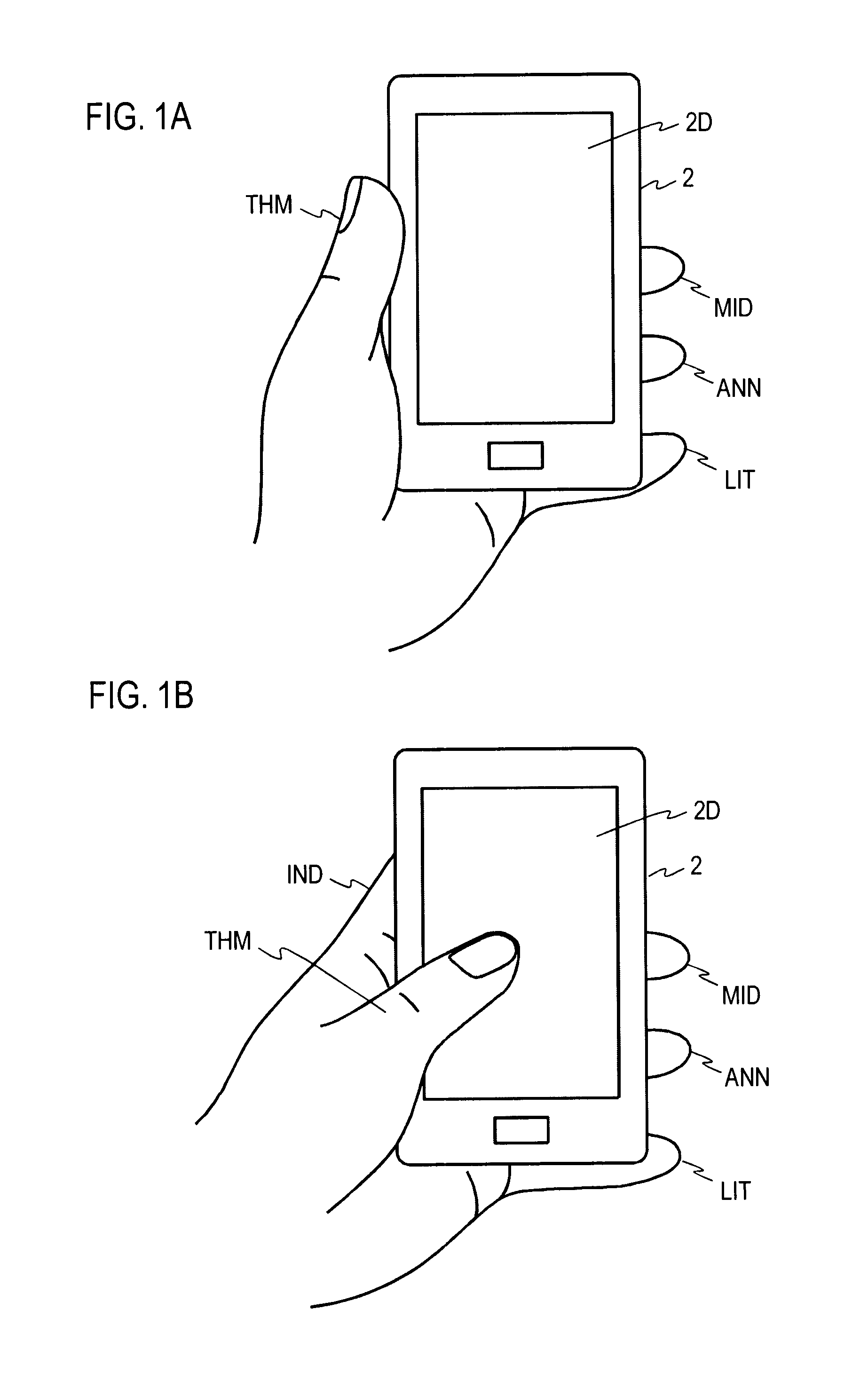
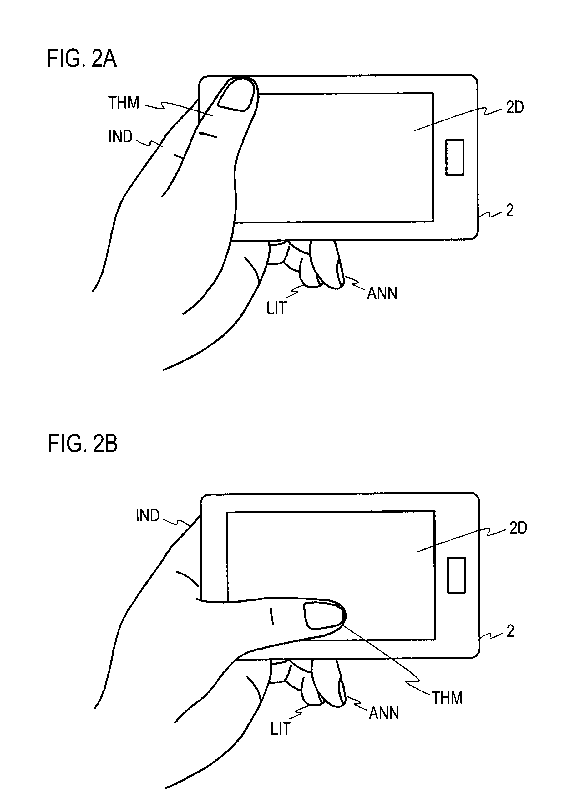
[0097]The portable terminal 10 according to the first embodiment will be described in detail with reference to FIGS. 12 and 13. FIG. 12 is a block diagram showing the configuration of the portable terminal 10 in this embodiment. FIG. 13 is a flowchart illustrating the operation of the portable terminal 10 in this embodiment. The portable terminal 10 in this embodiment includes the pressure sensor array 11, the gripping pressure logger 12, a gripping pressure change point detection unit 13, and the operation state determination section 14. The gripping pressure change point detection unit 13 includes the gripping pressure change amount calculation section 13a. The gripping pressure logger 12 records time-series changes in gripping pressure at each pressure sensor forming the pressure sensor array 11 (S12). The gripping pressure change amount calculation section 13a acquires the time-series changes in gripping pressure at each pressure sensor and determines whether the amount of chang...

second embodiment

[0099]The portable terminal 20 according to the second embodiment, which has higher accuracy in determining the operation state than the portable terminal 10 of the first embodiment, will be described next in detail with reference to FIGS. 14 and 15. FIG. 14 is a block diagram showing the configuration of the portable terminal 20 of this embodiment. FIG. 15 is a flowchart illustrating the operation of the portable terminal 20 of this embodiment. The portable terminal 20 of this embodiment includes the pressure sensor array 11, the gripping pressure logger 12, a gripping pressure change point detection unit 23, and the operation state determination section 24. The gripping pressure change point detection unit 23 includes the gripping pressure change amount calculation section 13a and the change frequency counting section 23b. This embodiment differs from the first embodiment in that the gripping pressure change point detection unit 13 in the first embodiment is replaced by the grippi...

third embodiment

[0102]The portable terminal 30 according to the third embodiment, which has an enhanced function of determining the operation state in comparison with the one in the portable terminal 10 of the first embodiment, will be described next in detail with reference to FIGS. 16 and 17. FIG. 16 is a block diagram showing the configuration of the portable terminal 30 in this embodiment. FIG. 17 is a flowchart illustrating the operation of the portable terminal 30 in this embodiment. The portable terminal 30 in this embodiment includes the pressure sensor array 11, the gripping pressure logger 12, a gripping pressure change point detection unit 13, the screen orientation acquisition section 31, and the operation state determination section 34. The gripping pressure change point detection unit 13 includes the gripping pressure change amount calculation section 13a. This embodiment differs from the first embodiment in that the screen orientation acquisition section 31, which is not included in ...


PUM


Abstract

A mobile information terminal to determine whether a user's operation state is one-handed operation or two-handed operation. The mobile information terminal includes a pressure sensor array that acquires a gripping pressure distribution; a gripping pressure logger that records time-series changes in gripping pressure at each pressure sensor forming the pressure sensor array; a gripping pressure change point detection unit that includes a gripping pressure change amount calculation section that acquires time-series changes in gripping pressure at each pressure sensor and determines whether the amount of change in gripping pressure per unit time exceeds a predetermined value at any pressure sensor; and an operation state determination section that determines the operation state of the user of the mobile information terminal is one-handed operation when the amount of change in gripping pressure per unit time exceeds the predetermined value at any pressure sensor.

Description

TECHNICAL FIELD[0001]The present invention relates to a mobile information terminal having a function to determine a user's operation state (one-handed or two-handed operation, etc.) from gripping features obtained when the mobile information terminal is gripped and an operation state determination method.BACKGROUND ART[0002]Mobile information terminals having a touch sensitive screen as a user interface have been coming into use in recent years. The user can intuitively operate the mobile information terminal with a touch sensitive screen by touching the screen with a finger or by sliding the finger on the screen. Many recent mobile information terminals incorporate an accelerometer, and those mobile information terminals can automatically switch the display orientation of the display screen in accordance of the direction of gravitational force sensed by the accelerometer. This allows the user to use the mobile information terminal in a variety of gripping states and operation stat...

Claims


Application Information

Patent Timeline
Patent Type & Authority Applications(United States)
IPC IPC(8): G06F3/041
CPCG06F3/0414G06F1/1684G06F2203/04105G06F3/017G06F3/0482G06F3/04886G06F3/0393G06V40/107G06V40/11
Inventor MORINAGA, YASUOTSUKAMOTO, MASAKATSUOTA, MANABUHIGUCHI, TAKESHI
Owner NTT DOCOMO INC
Why Eureka
Try Eureka