Radar sensor for a motor vehicle, motor vehicle and communication method

a technology a sensor is applied in the field of a radar sensor for a motor vehicle, which can solve the problems of complex hardware, difficult to avoid accidents, and high hardware cost, and achieve the effect of reducing hardware complexity and causing delays in the bus system

Active Publication Date: 2014-02-06
AUDI AG
View PDF6 Cites 87 Cited by
  • Summary
  • Abstract
  • Description
  • Claims
  • Application Information

AI Technical Summary

Benefits of technology

[0010]According to the invention, it is proposed to combine the radar sensor and the car-to-car communication in a single device by using the same antenna arrangement, so that the radar sensor of the invention can also act as a communication device. In this way, latencies caused by the transmission in the bus system of the motor vehicle and processing in an external communication device can be significantly reduced, providing additional cost benefits or advantages due to reduced hardware complexity, because of the implementation of both functions in the same device. When the radar sensor itself already has a controller, only the controller must be expanded with a suitable functionality by adding signal processing devices for car-to-car communication.
[0025]According to another advantageous feature of the present invention, a plurality of radar sensors covering the entire surroundings of the vehicle may be provided. In other words, the motor vehicle may have a sufficient number of radar sensors for a uniform 360° radar view, so that in spite of the directional emission of the messages via the radar sensor and its antenna arrangement, respectively, a car-to-car communication can be realized in all directions. It should be emphasized again that it is advantageous when, even with a 360° range view, messages can also be sent and received directionally, so that, for example, when a collision should be avoided, the particular radar sensor, in whose receiving range the potential collision object or another affected road users is located, sends out a corresponding message.

Problems solved by technology

Whereas the time window until a collision are usually very narrow in critical situations, it is evident that the described procedure may take quite some time before the actuator or the driver of the second vehicle can react, making it almost impossible to avoid an accident.
Another disadvantage of the conventional solution is the complex and expensive hardware.

Method used


Image

  • Radar sensor for a motor vehicle, motor vehicle and communication method
  • Radar sensor for a motor vehicle, motor vehicle and communication method
  • Radar sensor for a motor vehicle, motor vehicle and communication method

Examples


Embodiment Construction

[0033]Throughout all the figures, same or corresponding elements may generally be indicated by same reference numerals. These depicted embodiments are to be understood as illustrative of the invention and not as limiting in any way. It should also be understood that the figures are not necessarily to scale and that the embodiments are sometimes illustrated by graphic symbols, phantom lines, diagrammatic representations and fragmentary views. In certain instances, details which are not necessary for an understanding of the present invention or which render other details difficult to perceive may have been omitted.

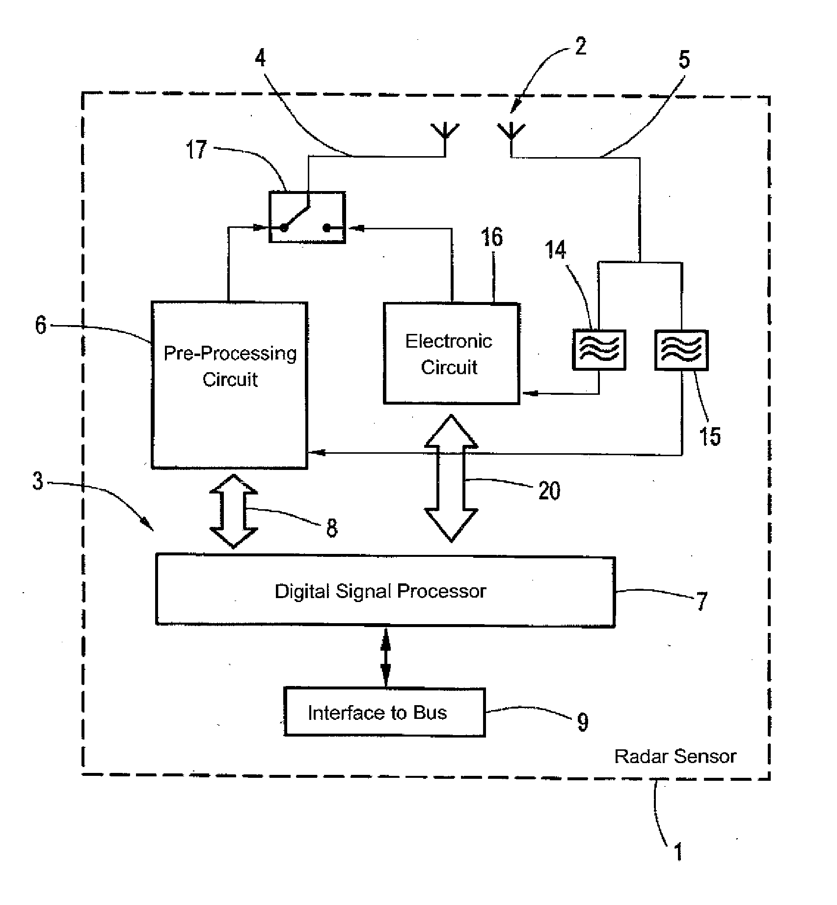
[0034]Turning now to the drawing, and in particular to FIG. 1, there is shown a schematic diagram of a radar sensor 1 according to the invention, which can also be used as a communication device for car-to-car communication, since the antenna arrangement 2 can be controlled by a controller 3 for both transmitting and receiving radar signals as well as for transmitting and re...


PUM


Abstract

A radar sensor for a motor vehicle has at least one antenna arrangement for transmitting and receiving radar signals and a controller for controlling the operation of the antenna arrangement. The controller evaluates the received radar signals. The controller also operates the antenna arrangement to transmit and / or receive messages in a car-to-car communication.

Description

CROSS-REFERENCES TO RELATED APPLICATIONS[0001]This application claims the priority of German Patent Application, Serial No. 10 2012 015 250.7, filed Aug. 1, 2012, pursuant to 35 U.S.C. 119(a)-(d), the content of which is incorporated herein by reference in its entirety as if fully set forth herein.BACKGROUND OF THE INVENTION[0002]The present invention relates to a radar sensor for a motor vehicle, with at least one antenna arrangement for transmitting and receiving radar signals and a controller configured for controlling operation of the antenna arrangement and for evaluating the received radar signals. In addition, the invention relates to a motor vehicle and a communication method.[0003]The following discussion of related art is provided to assist the reader in understanding the advantages of the invention, and is not to be construed as an admission that this related art is prior art to this invention.[0004]Radar sensors, also for use in motor vehicles, are known in the art. In t...

Claims


Application Information

Patent Timeline
Patent Type & Authority Applications(United States)
IPC IPC(8): G01S13/93G01S13/02G01S13/931
CPCG01S13/0209G01S13/931G01S7/006G01S13/42G01S13/58G01S2013/9316
Inventor KHLIFI, RACHID
Owner AUDI AG
Why Eureka
Try Eureka