Pendant light fixture

a technology for a light fixture and a cord is applied in the field of apendant light fixtures, which can solve the problems of short lamp shades, unclean and balanced appearance, and short lampshades, and achieve the effects of reducing the length of the cord, streamlined the appearance of the fixture, and balanced aesthetics

Inactive Publication Date: 2014-02-06
WORTH HOME PROD
View PDF11 Cites 10 Cited by
  • Summary
  • Abstract
  • Description
  • Claims
  • Application Information

AI Technical Summary

Benefits of technology

[0003]A pendant lamp according to various embodiments allows a user to install a standard floor or table lampshade on the pendant fixture. In particular embodiments, the pendant body is formed from two parts that attach to one another via a coupling. A flexible C-shaped portion of the power cord extends between the pendant's two primary body parts to allow the body parts to be moved with respect to one another. Moreover, once the body parts are coupled together, the C-shaped portion of the cord is adjustable so that the length of the cord can be reduced to streamline the appearan

Problems solved by technology

In certain current lighting arrangements, when fitting a table or standing lampshade to a pendant

Method used


Image

  • Pendant light fixture
  • Pendant light fixture
  • Pendant light fixture

Examples


first alternate embodiment

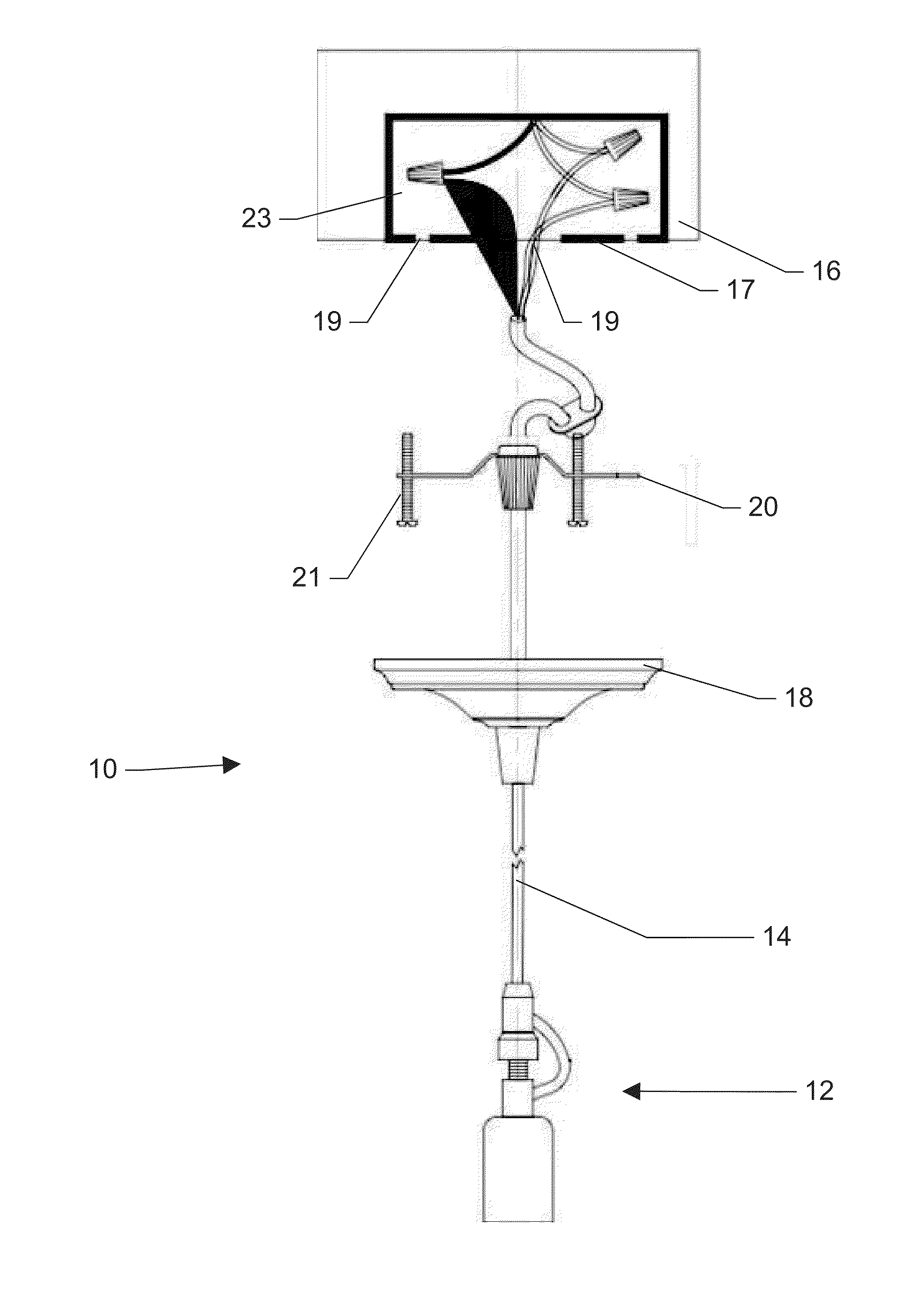
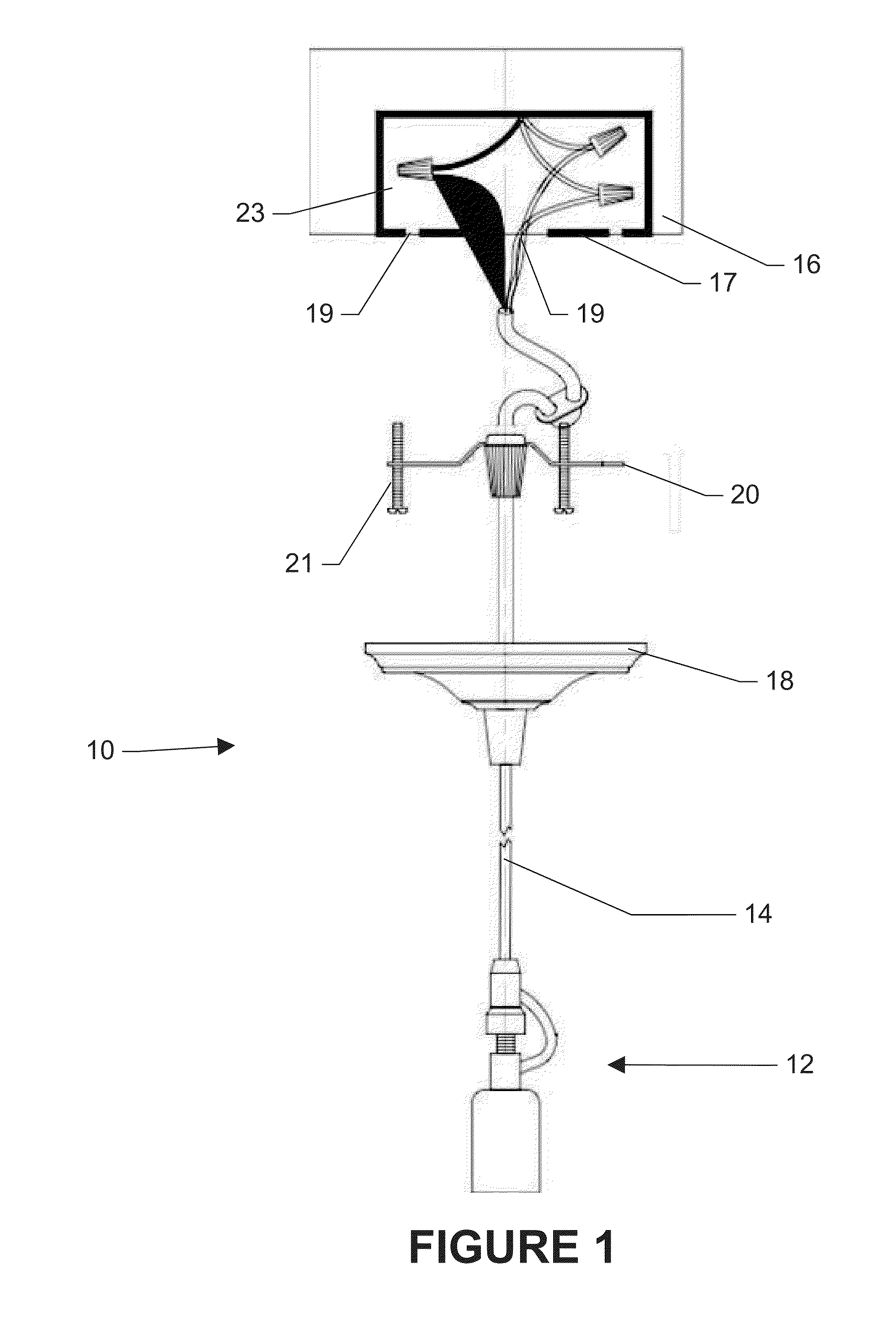
[0025]As shown in FIG. 4, a pendant lamp similar to that shown in FIG. 3 is illustrated having a pendant body 12, a power cord 14, a canopy cover 18, a power cord reel 64 and a light adapter 66. For ease of description, the overall pendant light illustrated in FIG. 4 is substantially the same as the light illustrated in FIG. 1, except for the power cord reel 64 and light adapter 66. Adapter 66 is configured to allow the user to convert a recessed light fixture into a hanging pendant lamp. In particular, an end 67 of light adapter 66 is sized and threaded similar to a standard light bulb so that the light adapter 66 can be inserted and screwed into an existing recessed light bulb socket. Thus, to install the pendant lamp shown in FIG. 4, the user inserts and screws the light adapter 66 into an existing light bulb socket in a recessed light fixture, and slides canopy 18 upward until it is flush against the ceiling. In this configuration, canopy 18 conceals the power cord reel and the ...

second alternate embodiment

[0028]Referring to FIG. 5, in yet another alternate embodiment, a pendant lamp 10, which is substantially similar to the pendant lamps of FIGS. 1 and 4 is illustrated having a plug adapter 68. In this embodiment, the pendant lamp can be installed using hooks that hold the power cord along the ceiling so that the plug drops adjacent a power outlet on the wall and its other end with its light socket drops the power cord in the desired room location. Thus, the pendant lamp of this embodiment can be easily installed and removed by inserting or removing the plug from an outlet and not require any ceiling power receptacle. Additionally, a series of pendant lamps may be installed using a power strip that accepts a plug.

Conclusion

[0029]With reference to the present disclosure, various pendant lamp fixtures are disclosed that allows a user install a variety of standard lampshades on the pendent fixture. The pendant lamp is formed with a flexible C-shaped power cord portion that provides flex...


PUM


Abstract

A pendant fixture comprising a first body portion having a threaded stud formed thereon, wherein the threaded stud is configured to receive a spider fitting of a lampshade when the lampshade is installed on the pendant fixture. A second body portion having a first half defining a threaded bore therein and a second half defining a second bore therethrough is rotatably coupled to the first body portion by the threaded stud and bore. A power cord having a first end for mounting to a structure, and a second end that is received through the second body portion second bore provides power to the first body portion. A length of power cord adjacent to the power cord second end defines a flexible and adjustable C-shaped cord portion intermediate the first body portion and the second body portion.

Description

CLAIM OF PRIORITY[0001]This application claims the benefit of and incorporates by reference, in its entirety, U.S. Provisional Patent Application No. 61 / 677,753, filed Jul. 31, 2012 and entitled “Pendant Light Fixture.”BACKGROUND[0002]Pendant lamps, e.g., lamps which hang from a ceiling or other elevated support by a chain, cable, or even from a power cord, have long been popular illumination devices in homes and elsewhere. Recently, commercial interest has been shown in fitting a pendant light fixture with standard floor and table lampshades. In most cases, standard floor and table lamps are constructed with a spider-type fitter ring that is too smaller in diameter to accept a pendant fixture's bulb socket, which is larger and typically used in conjunction with a socket ring to hold the pendant shade. In certain current lighting arrangements, when fitting a table or standing lampshade to a pendant light fixture, certain lampshades are two short and do not provide a clean and balanc...

Claims


Application Information

Patent Timeline
IPC IPC(8): F21V21/008
CPCF21V21/008F21V27/00F21S8/061F21V23/06
Inventor MACHIORLETTE, STEVEN C.
Owner WORTH HOME PROD
Why Eureka
Try Eureka