Microphone Assembly

a technology of microphones and components, applied in the direction of microphone structural associations, loudspeakers, semiconductor electrostatic transducers, etc., can solve the problems of reducing the size of the devices in which the microphones are deployed, and previous attempts have generally encountered limitations as to how much of a reduction can be made without affecting the performance of the microphon

Inactive Publication Date: 2014-02-06
KNOWLES ELECTRONICS INC
View PDF2 Cites 40 Cited by
  • Summary
  • Abstract
  • Description
  • Claims
  • Application Information

AI Technical Summary

Problems solved by technology

The devices in which microphones are deployed have become smaller over time.
Although previous attempts have been made to reduce the size of microphones, these previous attempts have generally encountered limitations as to how much of a reduction could be made without affecting the performance of the microphone.

Method used


Image

  • Microphone Assembly
  • Microphone Assembly
  • Microphone Assembly

Examples


Embodiment Construction

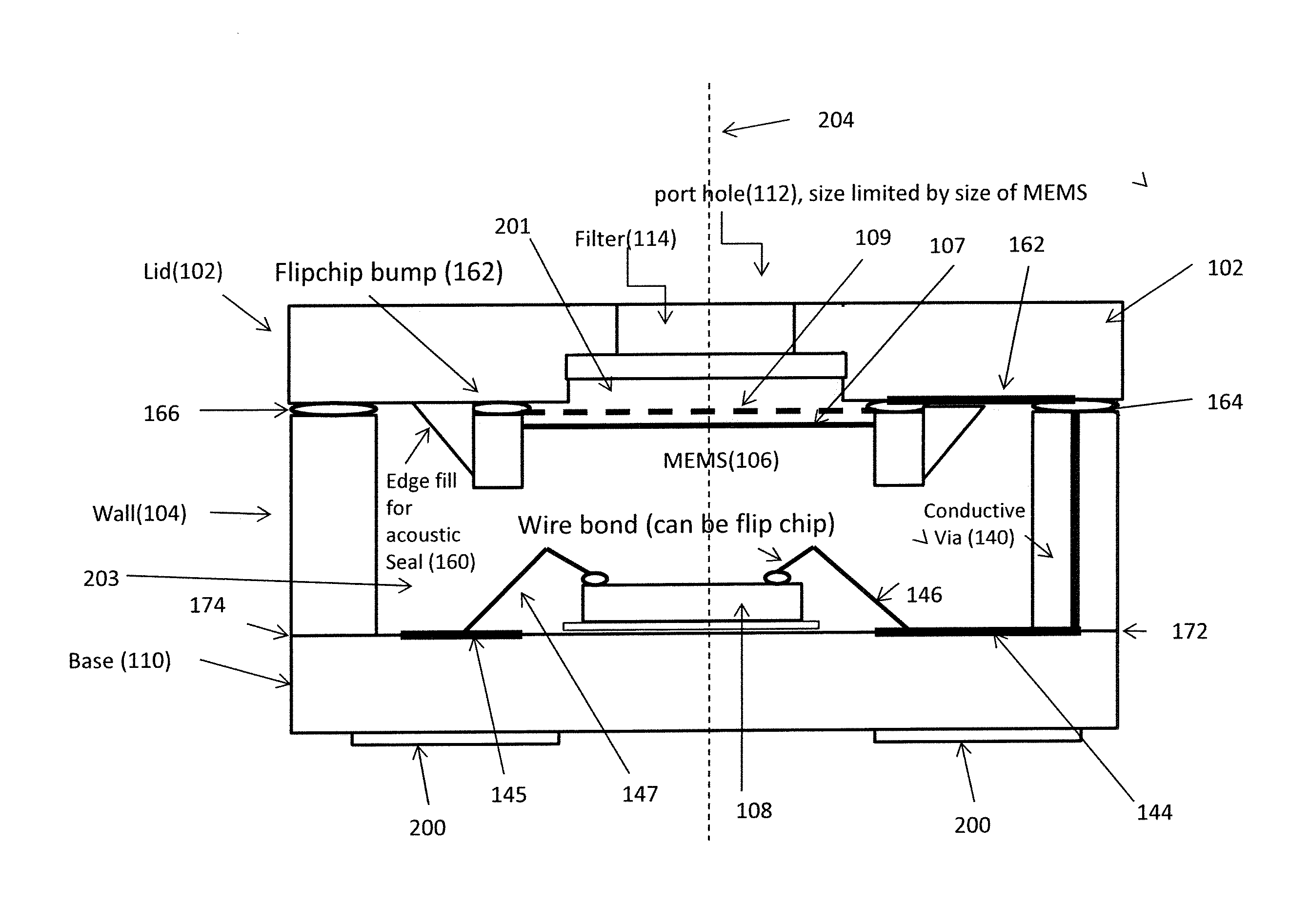
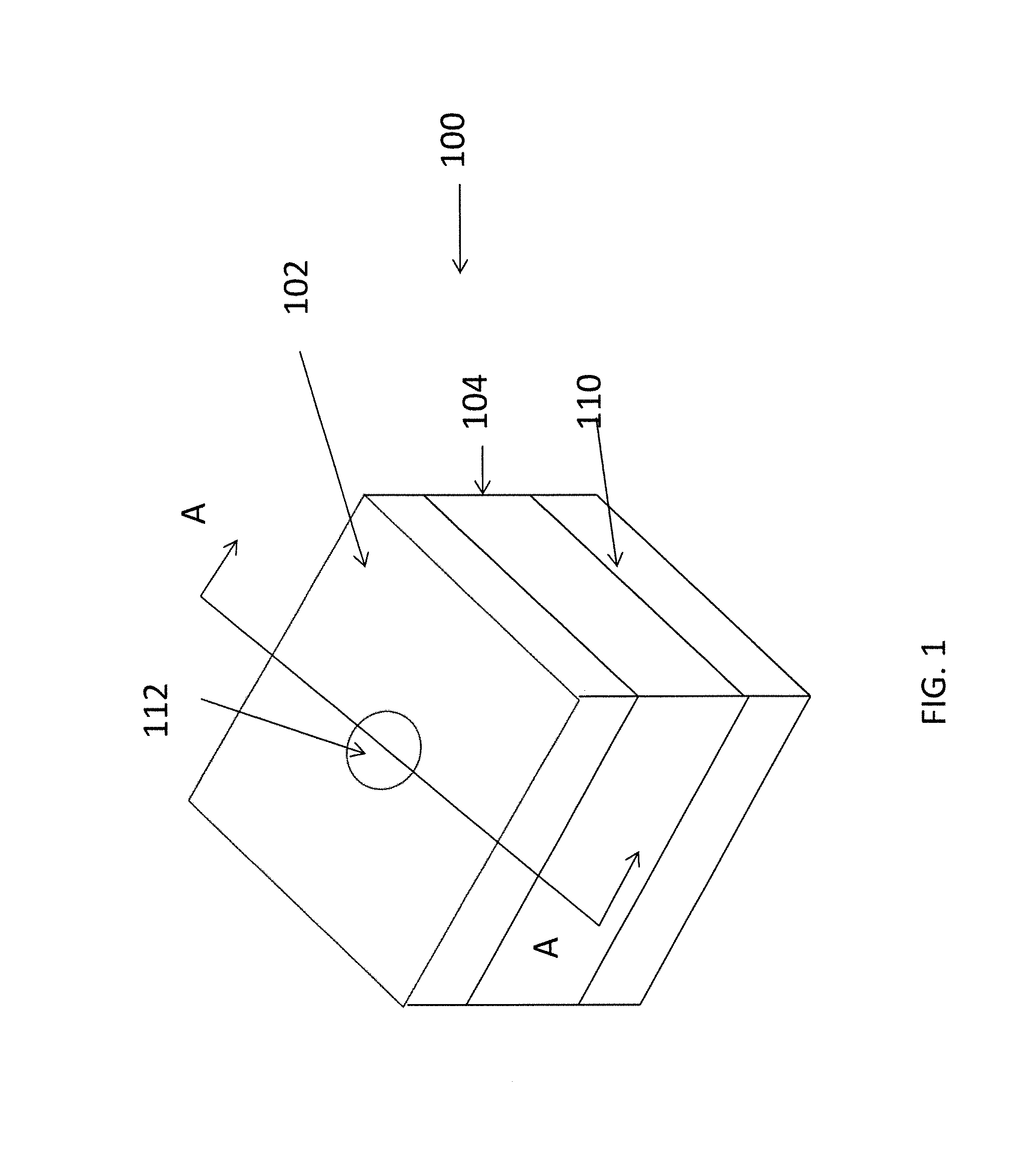
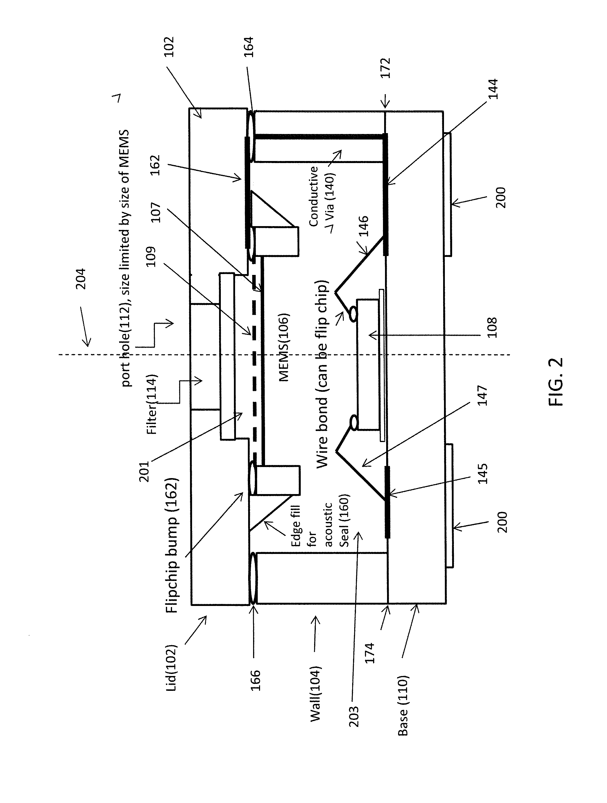
[0022]In the approaches described herein, a microphone assembly with a small form factor (e.g., overall assembly dimensions between approximately 1 mm to 3 mm (for one side) or 12 mm to 32 mm (total) for both top and bottom port architectures) is provided. In another aspect, the assembly provided in a layout that is a square (or approximately or substantially a square) in configuration. Other configurations are possible. The small form factor permits the microphone assembly to be used in small devices (e.g., devices where reduced size is desirable) such as cellular phones, hearing instruments, and computers.

[0023]In many of these embodiments, a microphone assembly includes a lid that is coupled to a wall portion. The wall is disposed to a base portion. The wall portion includes and defines a cavity formed therein. A port is disposed in one of either the base portion or the lid. A MEMS device and an integrated circuit are disposed in the cavity. One of the MEMS device or the integrat...


PUM


Abstract

A Microelectromechanical system (MEMS) assembly includes a cover, a substrate, at least one wall disposed and between and attached to the cover and the substrate, a MEMS device disposed at the cover and an integrated circuit disposed at the substrate. The integrated circuit and the MEMS device are disposed one over the other and electrically connected together at least in part by conduits that extend through the walls. Alternatively, the MEMS device may be disposed on the substrate and the integrated circuit disposed on the base.

Description

CROSS REFERENCE TO RELATED APPLICATION[0001]This patent claims benefit under 35 U.S.C. §119 (e) to U.S. Provisional Application No. 61 / 678,186 entitled “Microphone Assembly” filed Aug. 1, 2012, the content of which is incorporated herein by reference in its entirety.TECHNICAL FIELD[0002]This application relates to the acoustic devices and more specifically to the components that are used in these devices.BACKGROUND OF THE INVENTION[0003]Various types of acoustic devices have been used over the years. One example of an acoustic device is a microphone and another example is a receiver. Generally speaking, a microphone picks up sound and converts the sound into an electrical signal while a receiver takes an electrical signal and converts the electrical signal into sound.[0004]A microphone typically includes a microelectromechanical (MEMS) device and in some cases an integrated circuit. The MEMS device receives acoustic energy (sound) and converts this into an electrical signal. The MEM...

Claims


Application Information

Patent Timeline
Patent Type & Authority Applications(United States)
IPC IPC(8): H04R23/00
CPCH04R23/00H04R1/04H04R1/06H04R19/005H04R19/04H04R2201/003
Inventor LIM, TONY K.WANG, QINGVOS, SANDRA F.
Owner KNOWLES ELECTRONICS INC
Why Eureka
Try Eureka