Cooling system control in distributed antenna systems

a cooling system and antenna technology, applied in the direction of electrical apparatus construction details, instruments, wireless communication, etc., can solve the problems of increasing friction, increasing drag on the fan motor, and power supply generation considerable hea

Active Publication Date: 2014-02-06
CORNING OPTICAL COMM LLC
View PDF5 Cites 63 Cited by
  • Summary
  • Abstract
  • Description
  • Claims
  • Application Information

AI Technical Summary

Problems solved by technology

Power supplies generate considerable heat, and often fans are used to dissipate the heat generated during operation of the distributed antenna system.
However, as cooling fans continue to run, the drag on the fan motor will increase over time.
This drag typically results from increased friction in the fan's motor bearings resulting from the limited life of the bearing lubrication.
The drag can also be caused by an increase in the fan's static pressure, such as when debris accumulates in the fan filter.

Method used


Image

  • Cooling system control in distributed antenna systems
  • Cooling system control in distributed antenna systems
  • Cooling system control in distributed antenna systems

Examples


Embodiment Construction

[0026]Embodiments disclosed in the detailed description include power distribution modules having cooling requirements in distributed antenna systems (DASs). In embodiments disclosed herein, the power distribution modules can be installed in and connected to a power unit for providing power to a power-consuming DAS component(s), such as a remote antenna unit(s) (RAU(s)). Main power is provided to the power unit and distributed to power distribution modules in the power unit. Power from the main power is distributed by each of the power distribution modules to any power-consuming DAS components connected to the power distribution modules. The power distribution modules distribute power to the power-consuming DAS components to provide power for DAS components.

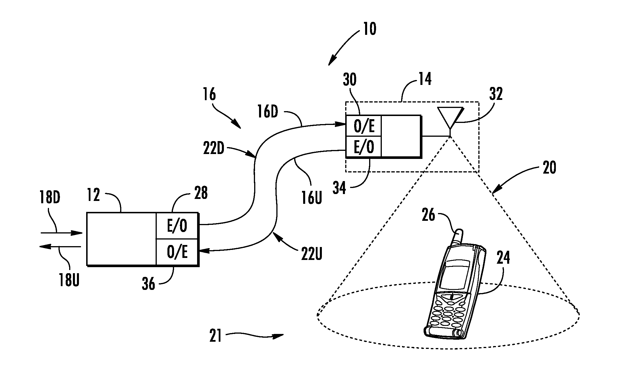
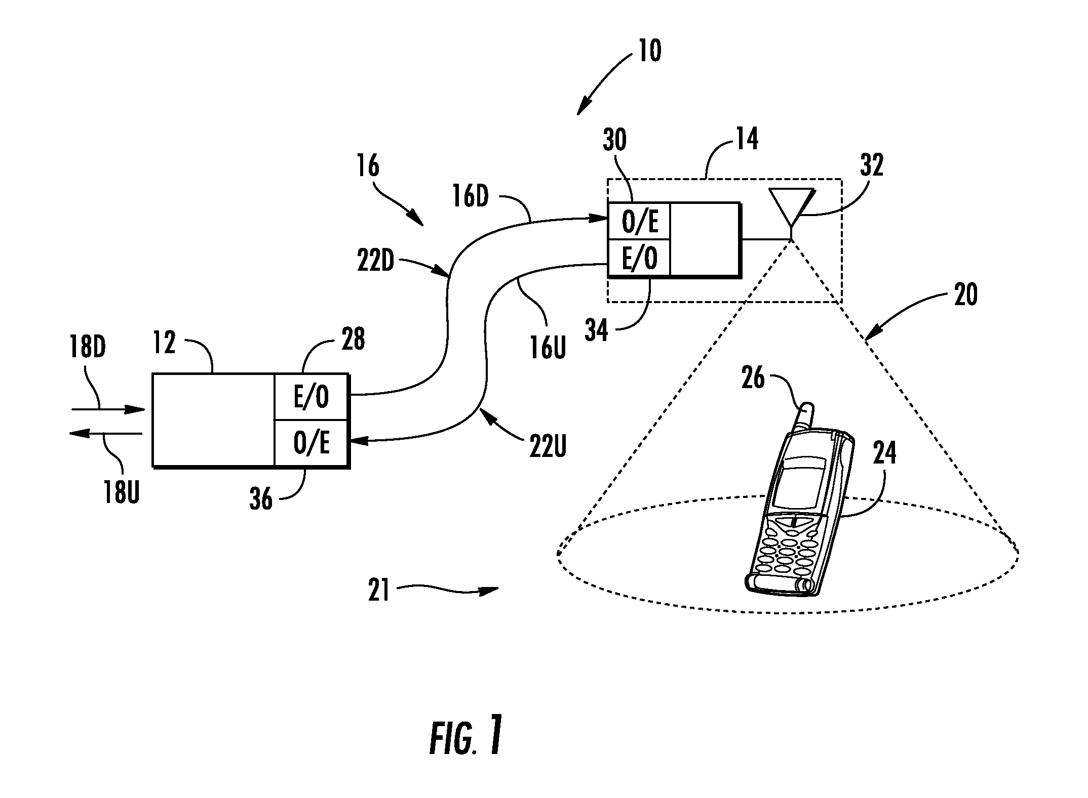
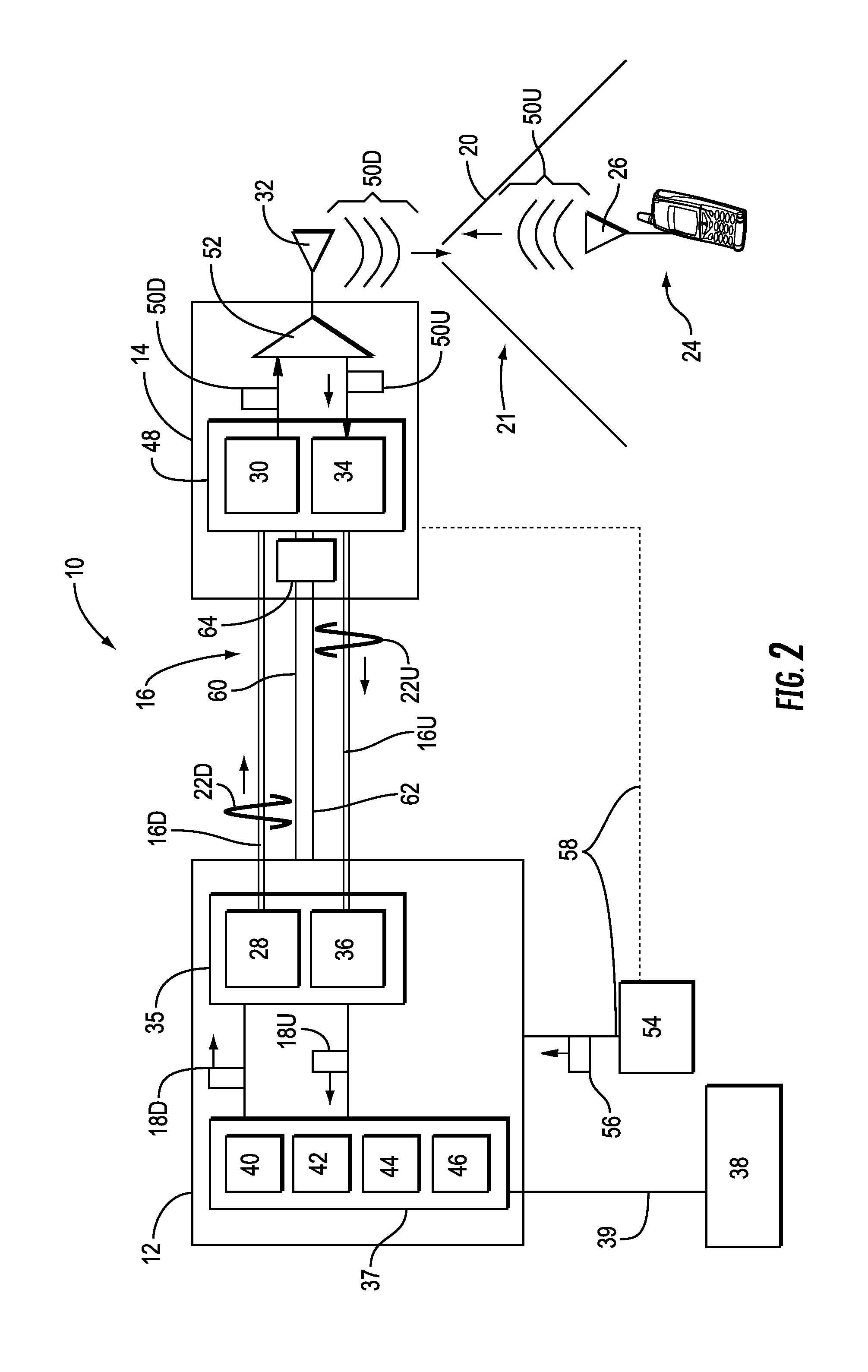
[0027]Before discussing examples of cooling system monitoring and control in distributed antenna systems (DASs), exemplary distributed antenna systems capable of distributing RF communications signals to distributed or remote ant...


PUM


Abstract

Power distribution modules in distributed antenna systems include fan monitoring circuits for indicating an alarm condition to head-end equipment. The alarm condition can be used by system operator/owners that a fan is drawing excessive power, thereby detracting from system performance, or indicating that the fan may fail. The alarm condition signal can be returned to the head-end equipment via an uplink communication path between a remote unit powered by the module and the head-end equipment.

Description

PRIORITY APPLICATION[0001]This application claims the benefit of priority under 35 U.S.C. §119 of U.S. Provisional Application No. 61 / 677,741 filed on Jul. 31, 2012 the content of which is relied upon and incorporated herein by reference in its entirety.RELATED APPLICATIONS[0002]This application is related to PCT Application No. PCT / US11 / 61761, filed Nov. 22, 2011, to U.S. patent application Ser. No. 12 / 466,514, filed May 15, 2009, and to U.S. application Ser. No. 13 / 899,118, filed May 21, 2013, which are incorporated herein by reference in their entireties.BACKGROUND[0003]1. Field of the Disclosure[0004]The technology of the disclosure relates to systems and methods for monitoring cooling systems in a distributed antenna system.[0005]2. Technical Background[0006]Wireless communication is rapidly growing, with increasing demands for high-speed mobile data communication. As an example, so-called “wireless fidelity” or “WiFi” systems and wireless local area networks (WLANs) are being ...

Claims


Application Information

Patent Timeline
Patent Type & Authority Applications(United States)
IPC IPC(8): H04B10/07
CPCH04B10/07H04B10/25753H04W88/085H02H7/093H05K7/20209G06F1/206H04B10/808H05K7/2019
Inventor COX, TERRY DEANHAZANI, AMI
Owner CORNING OPTICAL COMM LLC
Why Eureka
Try Eureka