Combination of thin-walled pipe and joint, and method for forming the same

a thin-walled metal pipe and joint technology, applied in the direction of hose connection, manufacturing tools, mechanical equipment, etc., can solve the problems of increasing assembly skills, labor intensity, assembly costs, and labor intensity, and achieves convenient operation, time and material saving, and reliable connection

Inactive Publication Date: 2014-02-13
PANG HAOHUI +1
View PDF9 Cites 2 Cited by
  • Summary
  • Abstract
  • Description
  • Claims
  • Application Information

AI Technical Summary

Benefits of technology

[0007]In view of the above-described problems, the invention provides in one aspect a combination of a thin-walled metal pipe and a joint as well as a method for forming the combination. The method is simple, time and material-saving, and convenientin operation. The resulting combination is joined by a firm and reliable connection, and has excellent sealing properties. There is also a space provided between the metal pipe and the joint for buffering the thermal expansion of the metal pipe in case of temperature fluctuations.

Problems solved by technology

To connect pipes during assembly or to disconnect them when repair or maintenance is required, special tools are employed, which results in increased space requirements and increases labor intensity, assembly skills, and costs.
However, soldered side seams of thin-walled pipes are prone to cracking in the process of ring expansion.
Furthermore, in the case of leakage during pipe layering, ring expansion cannot be used because pipes are usually buried in concrete.

Method used


Image

  • Combination of thin-walled pipe and joint, and method for forming the same
  • Combination of thin-walled pipe and joint, and method for forming the same
  • Combination of thin-walled pipe and joint, and method for forming the same

Examples


Embodiment Construction

[0024]For further illustrating the invention, experiments detailing a combination of a thin-walled metal pipe and a joint and a method for forming the same are described below. It should be noted that the following examples are intended to describe and not to limit the invention.

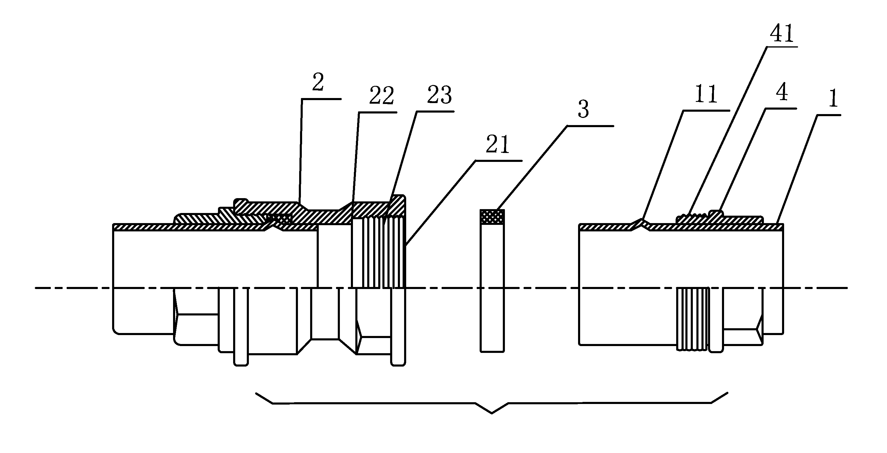
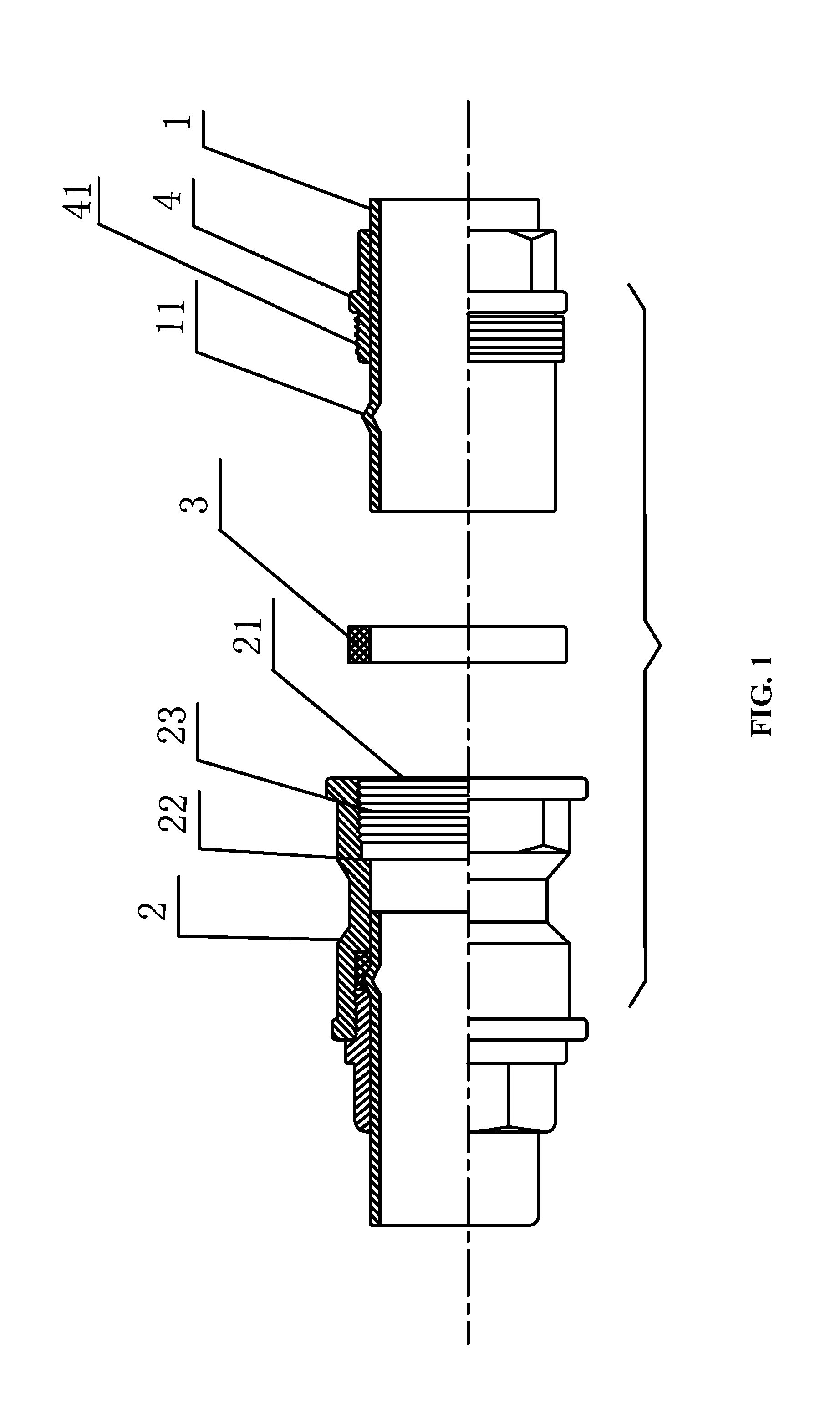
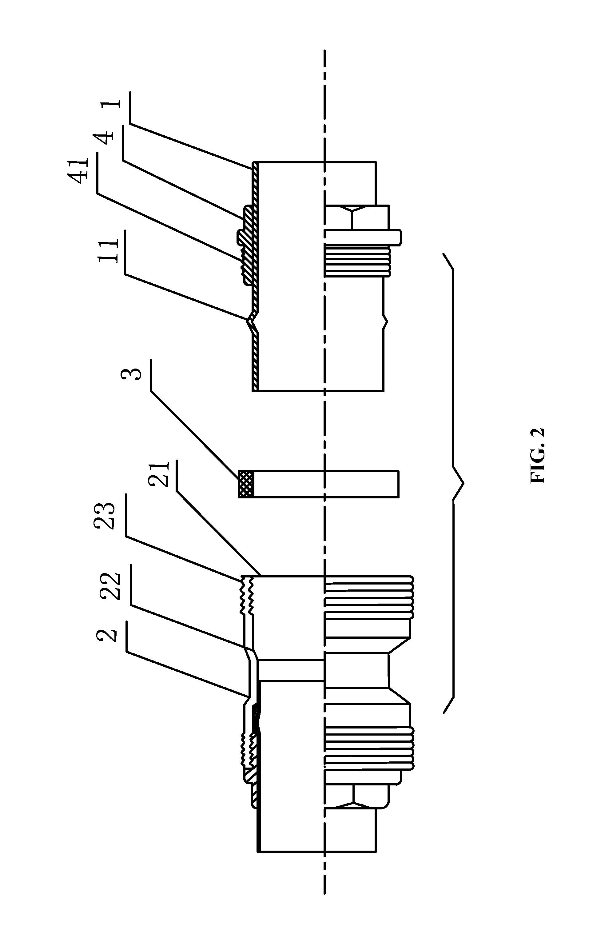
[0025]As shown in FIG. 1, a combination of a thin-walled metal pipe and a joint comprises a thin walled stainless steel pipe 1, a joint 2, a rubber sealing ring 3, and a socket ring 4. The socket ring 4 comprises male thread 41. One end of the pipe 1 is pressed by a pair of pliers to yield a boss 11. One end of the joint 2 is provided an opening 21 for receiving the pipe 1. A step 22 is disposed at the bottom of the opening 21. An internal wall of the joint 2 comprises female thread 23 corresponding to the male thread 41 of the socket ring 4.

[0026]Upon assembly, the socket ring 4 is sleeved on the pipe 1. One end of the pipe 1 is pressed by a pair of pliers to yield the boss 11. The sealing ring 3 is sleeved...


PUM

PropertyMeasurementUnit
heightaaaaaaaaaa
heightaaaaaaaaaa
diameteraaaaaaaaaa

Abstract

A combination of a thin-walled metal pipe and a joint, including the thin-walled metal pipe, the joint, a sealing ring, and a socket ring. One end of the metal pipe is pressed by a pair of pliers to form a boss. One end of the joint is provided with an opening including a female thread for receiving the metal pipe. A step is disposed at the bottom of the opening. The socket ring comprises male thread corresponding to the female thread. The sealing ring and the socket ring are sleeved on the metal pipe and are separated by the boss. When the socket ring is screwed down, the female thread and the male thread cooperate with each other tightly, so that the socket ring leans against the boss and extrudes the sealing ring to press the step at the bottom of the opening to form a sealed combination.

Description

CROSS-REFERENCE TO RELATED APPLICATIONS[0001]This application is a continuation-in-part of International Patent Application No. PCT / CN2012 / 000558 with an international filing date of Apr. 25, 2012, and is also a continuation-in-part of International Patent Application No. PCT / CN2012 / 000687 with an international filing date of May 18, 2012, designating the United States, now pending, and further claims priority benefits to Chinese Patent Application No. 201110101039.9 filed Apr. 22, 2011, and to Chinese Patent Application No. 201110105752.0 filed Apr. 25, 2011, respectively. The contents of all of the aforementioned applications, including any intervening amendments thereto, are incorporated herein by reference. Inquiries from the public to applicants or assignees concerning this document or the related applications should be directed to: Matthias Scholl P.C., Attn.: Dr. Matthias Scholl Esq., 14781 Memorial Drive, Suite 1319, Houston, Tex. 77079.BACKGROUND OF THE INVENTION[0002]1. Fi...

Claims


Application Information

Patent Timeline
Patent Type & Authority Applications(United States)
IPC IPC(8): F16L19/02
CPCF16L19/0218Y10T29/49963
Inventor PANG, HAOHUI
Owner PANG HAOHUI
Why Eureka
Try Eureka