
Three-dimensional image display apparatus and three-dimensional image processing method

Active Publication Date: 2014-02-13
INNOLUX CORP
View PDF8 Cites 31 Cited by
  • Summary
  • Abstract
  • Description
  • Claims
  • Application Information

AI Technical Summary

Benefits of technology

The present invention is a 3D image display apparatus and processing method that aims to improve the display effect. It reduces cross-talk and image motion juddering issues, while increasing resolution. The apparatus includes an intensity calculating module and an image converting module that output intensity information based on position and original 3D image information. The 3D image processing module then outputs modified intensity information, which the display module uses to generate the modified 3D image.

Problems solved by technology

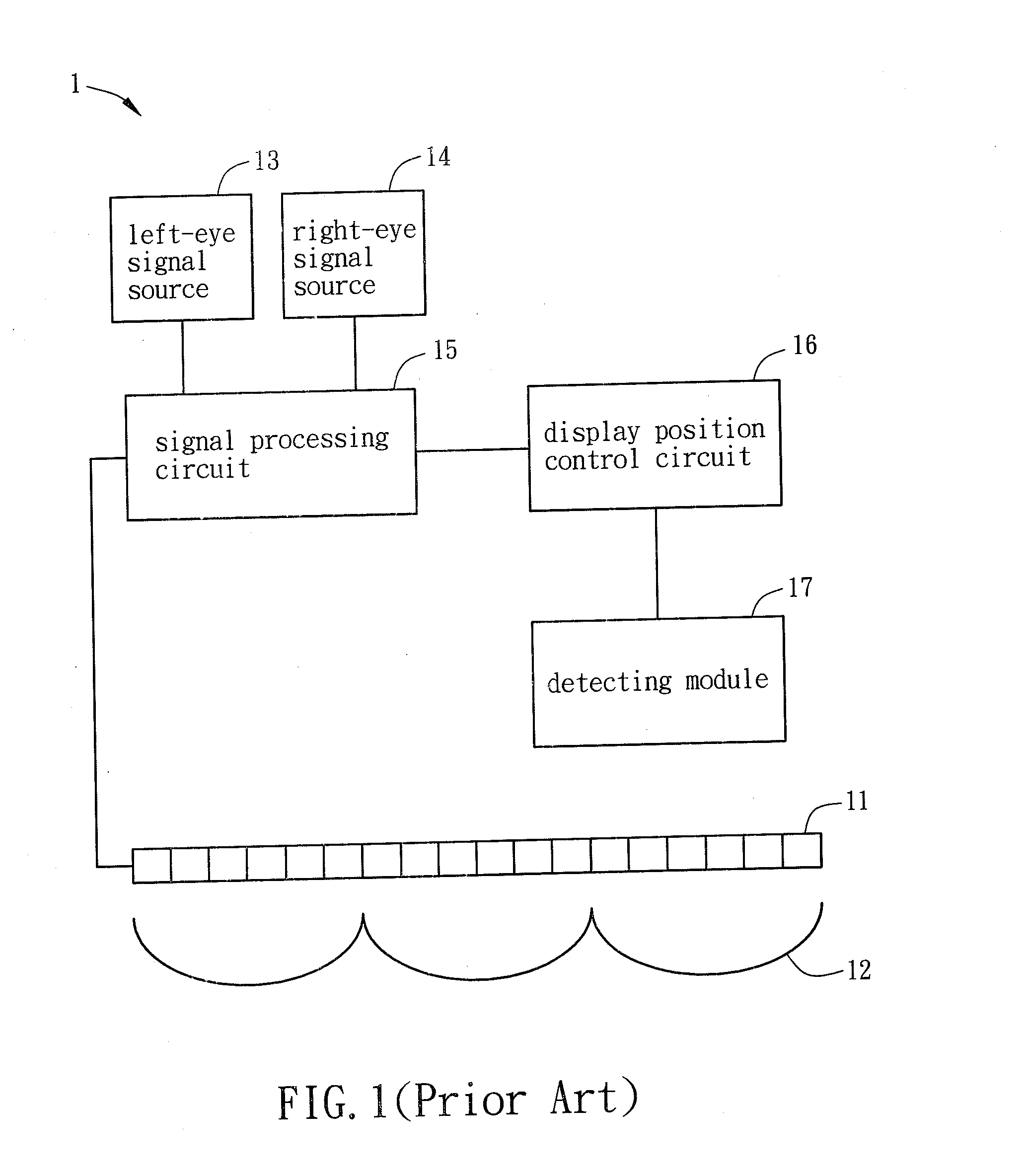
Although the conventional 3D image display apparatus 1 can adjust the pixels to display the left-eye signal or the right-eye signal according to the head position of the user, it still cannot avoid the undesired cross-talk issue generated as one eye of a user receives the left-eye signal and the right-eye signal simultaneously.
Furthermore the conventional 3D image display apparatus 1 need to consume at least six sub-pixels to avoid an image motion juddering issue that may happen when head position is changed, it leads to display resolution loss.

Method used


Image

  • Three-dimensional image display apparatus and three-dimensional image processing method
  • Three-dimensional image display apparatus and three-dimensional image processing method
  • Three-dimensional image display apparatus and three-dimensional image processing method

Examples


Embodiment Construction

[0029]The present invention will be apparent from the following detailed description, which proceeds with reference to the accompanying drawings, wherein the same references relate to the same elements.

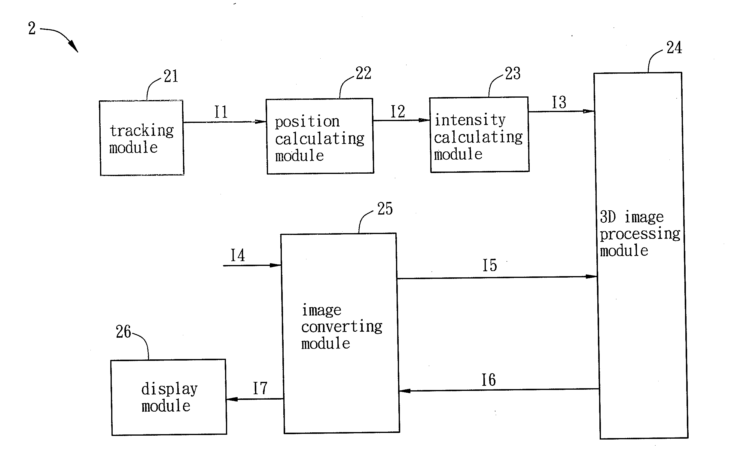
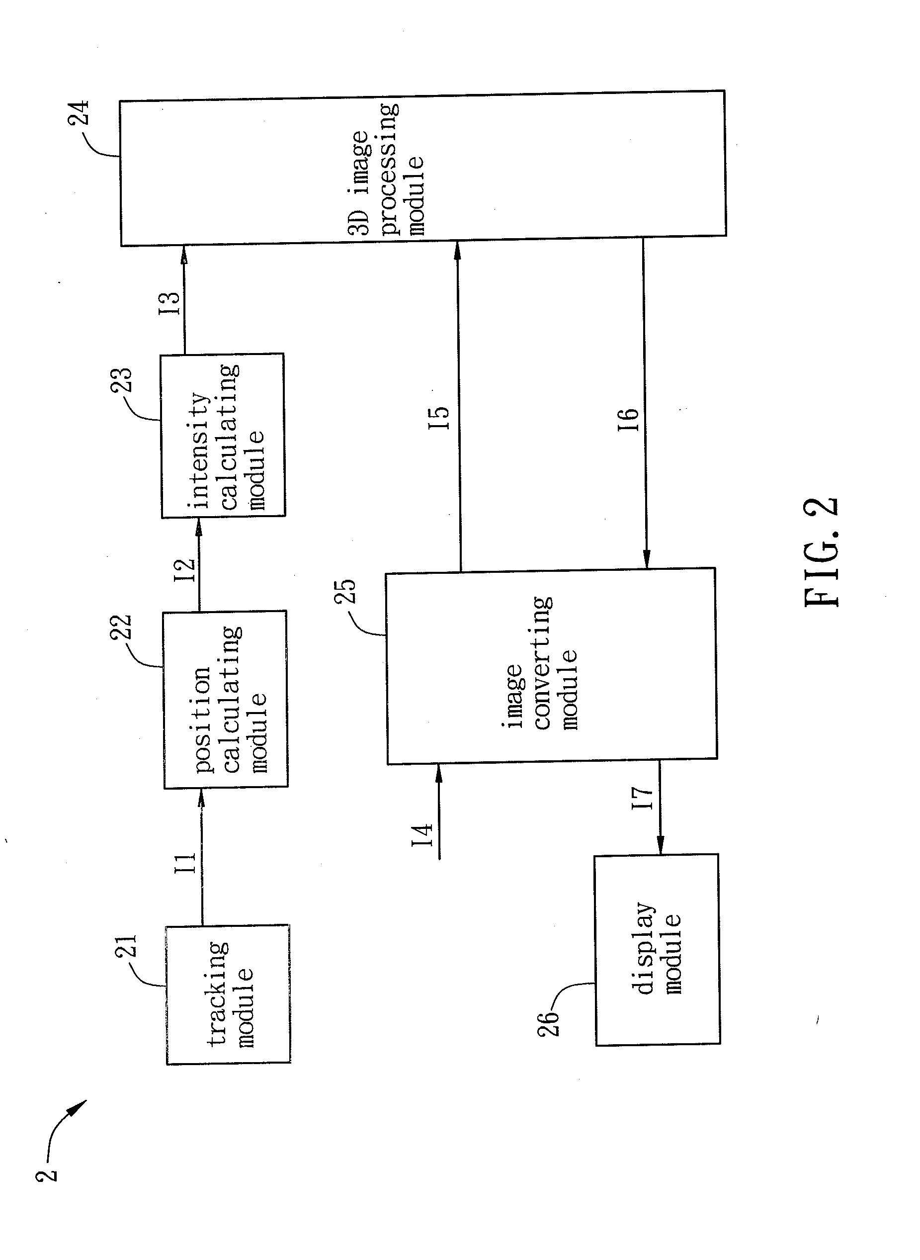
[0030]FIG. 2 is a schematic diagram showing a three-dimensional (3D) image display apparatus 2 according to a preferred embodiment of the present invention. The 3D image display apparatus 2 includes a tracking module 21, a position calculating module 22, an intensity calculating module 23, a 3D image processing module 24, an image converting module 25, and a display module 26.

[0031]The tracking module 21 is configured to track an object, such as the center point of each eye, the center point between the eyes, or the center point of the forehead. The tracking module 21 is continuously tracking the object so as to output the coordinate information I1 of the object in real time or once per frame time. Herein, the coordinate information I1 represents the 3D coordinate information of the l...


PUM


Abstract

A 3D image display apparatus includes a tracking module, a position calculating module, an intensity calculating module, a 3D image processing module, an image converting module and a display module. The tracking module tracks an object and outputs coordinate information of the object. The position calculating module outputs position information according to the coordinate information. The intensity calculating module outputs intensity coefficient information according to the position information. The 3D image processing module receives the intensity coefficient information. The image converting module outputs target intensity information to the 3D image processing module according to original 3D image information. The display module receives modified 3D image information. The 3D image processing module outputs modified intensity information to the image converting module according to the intensity coefficient information and the target intensity information, and then the image converting module outputs the modified 3D image information according the modified intensity information.

Description

BACKGROUND OF THE INVENTION[0001]1. Field of Invention[0002]The present invention relates to an image display apparatus and processing method, and in particular, to a three-dimensional (3D) image display apparatus and processing method.[0003]2. Related Art[0004]In general, three-dimensional (3D) image display apparatuses are categorized into stereoscopic display apparatuses and autostereoscopic display apparatuses (also referred to naked-eye type 3D image display apparatuses). Regarding to the stereoscopic display apparatus, the user has to wear a viewing aid, such as shutter glasses, so that the left and right eyes of the user can receive different images respectively, and thereby perceiving a 3D image. Regarding to the autostereoscopic display apparatus, a specially designed optical element is configured so as to allow the display apparatus to provide different images to the left and right eyes of a user respectively, so that the user can perceive a 3D image by naked eyes.[0005]FI...

Claims


Application Information

Patent Timeline
IPC IPC(8): G06T15/00G02B30/29G02B30/31
CPCH04N13/305H04N13/317H04N13/351H04N13/366H04N13/376H04N13/383G02B30/31G02B30/29G02B30/27
Inventor SUMI, NAOKI
Owner INNOLUX CORP
Learn More