Supercharge Your Innovation With Domain-Expert AI Agents!

Rotary diaphragm pump

a diaphragm pump and rotary technology, applied in the direction of rotary or oscillating piston engines, engine lubrication, rotary piston engines, etc., can solve the problems of reducing the mechanical efficiency and reducing the service life of hydraulically actuated pumps. achieve the effect of greater pumping capacity

Inactive Publication Date: 2014-02-13
KUWAIT UNIV
View PDF6 Cites 3 Cited by
  • Summary
  • Abstract
  • Description
  • Claims
  • Application Information

AI Technical Summary

Benefits of technology

The rotary diaphragm pump has a flexible diaphragm and frame assembly that creates a pumping action by moving the diaphragm. The pump has multiple chambers and an articulating mechanism that moves the diaphragm back and forth to change the volume of the chambers. The pump can be connected in various ways to create different types of pumps. The invention allows for greater pumping capacity from a single driveshaft by joining multiple cases.

Problems solved by technology

The stress imposed upon the diaphragm by being mechanically attached to other structure both about its periphery and its central area results in relatively large stress upon the diaphragm and correspondingly shortened life.
Various hydraulically actuated diaphragm pumps have been developed in an effort to reduce the stress on the diaphragm, but such hydraulically actuated pumps generally suffer from reduced mechanical efficiency in comparison to mechanically actuated planar diaphragm pumps.
Another disadvantage of such conventional diaphragm pumps is that a single diaphragm generally corresponds to a single pump chamber.
The efficiency and smoothness of operation of the pump is thus relatively limited in a manner somewhat analogous to a single cylinder reciprocating pump or engine, so that it has only one power stroke or pulse per revolution.
Conventional mechanically driven planar diaphragm pumps are incapable of providing such smooth fluid delivery unless equipped with additional components to smooth the pulses delivered from the pump.

Method used


Image

  • Rotary diaphragm pump
  • Rotary diaphragm pump
  • Rotary diaphragm pump

Examples


Embodiment Construction

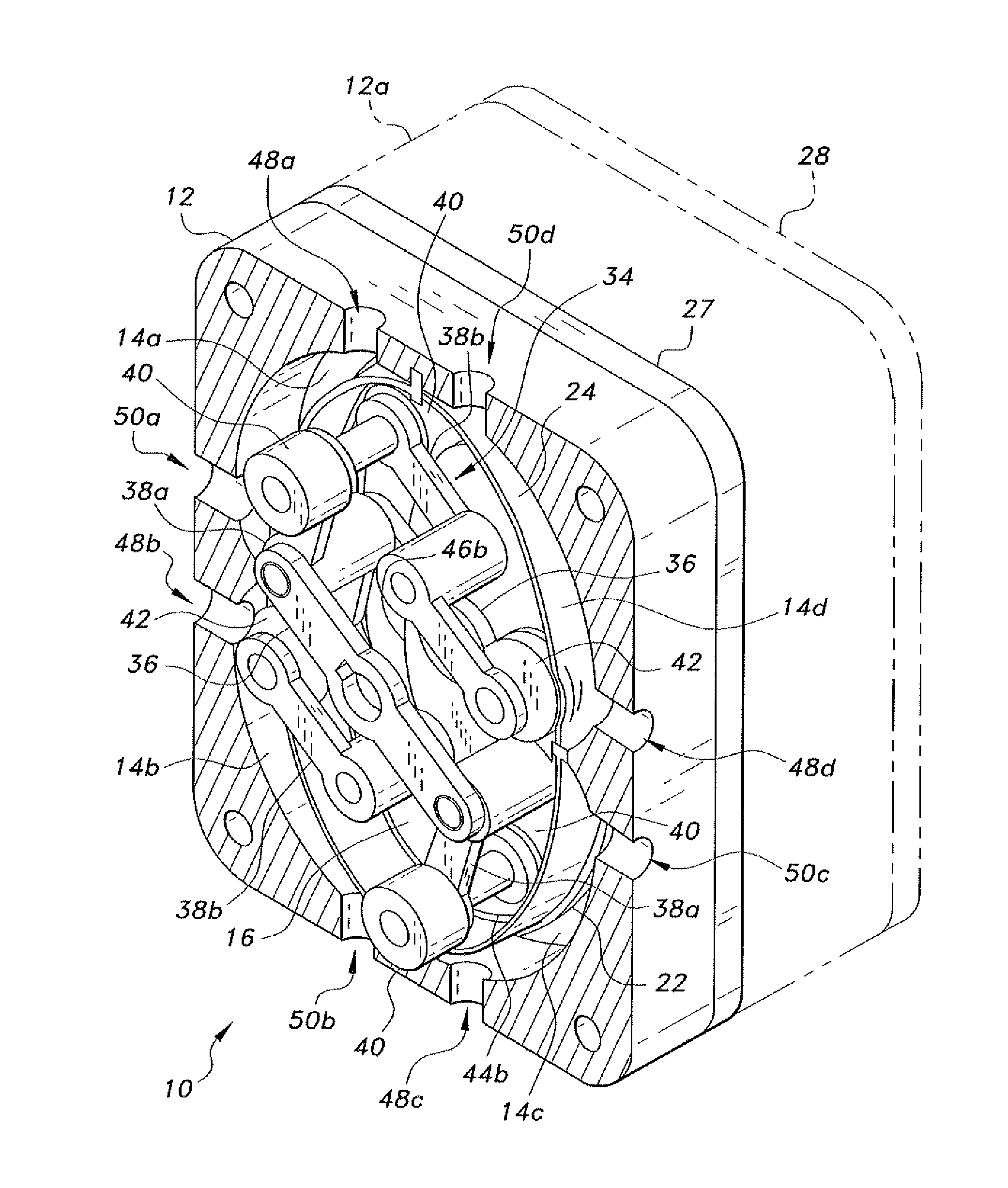
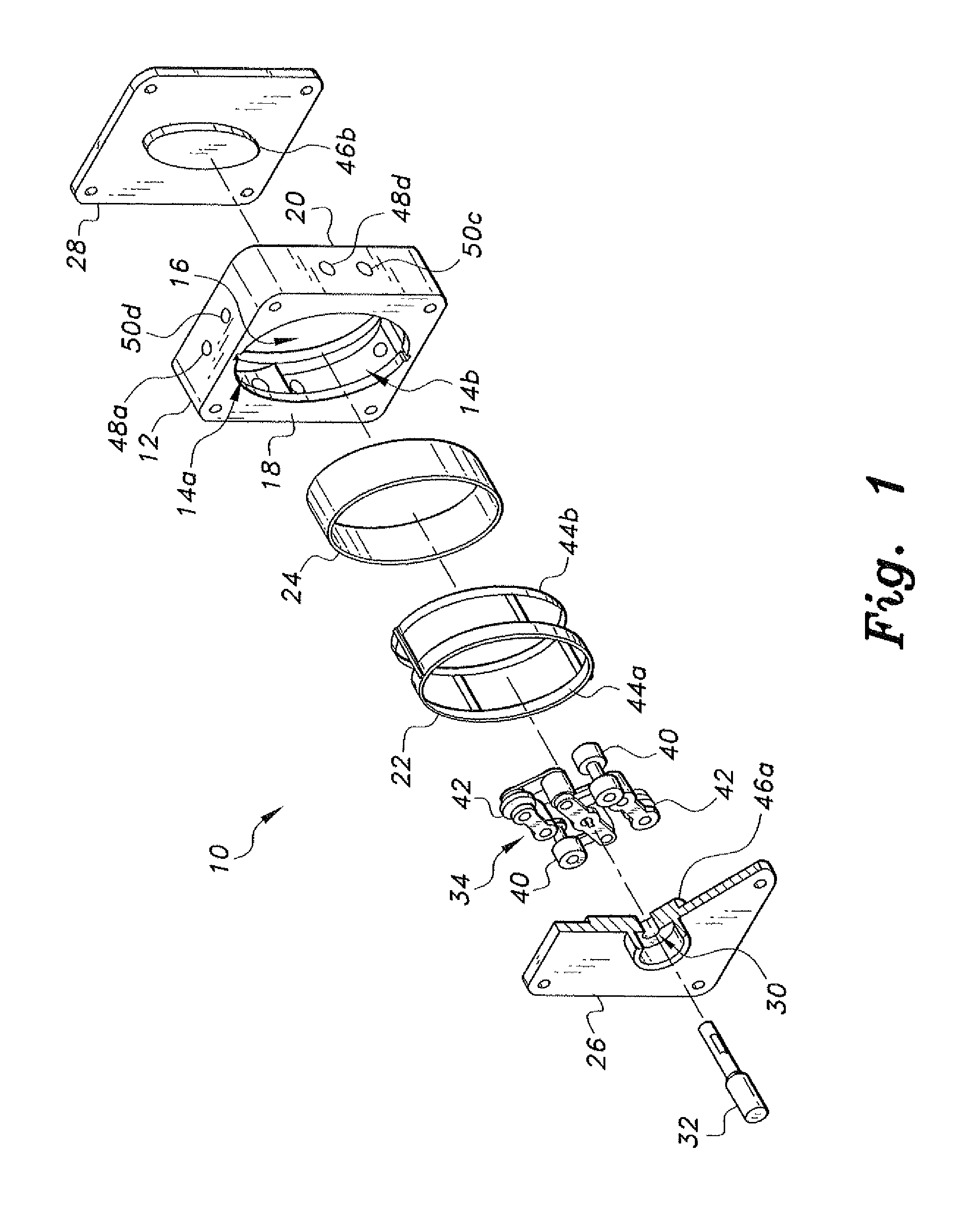
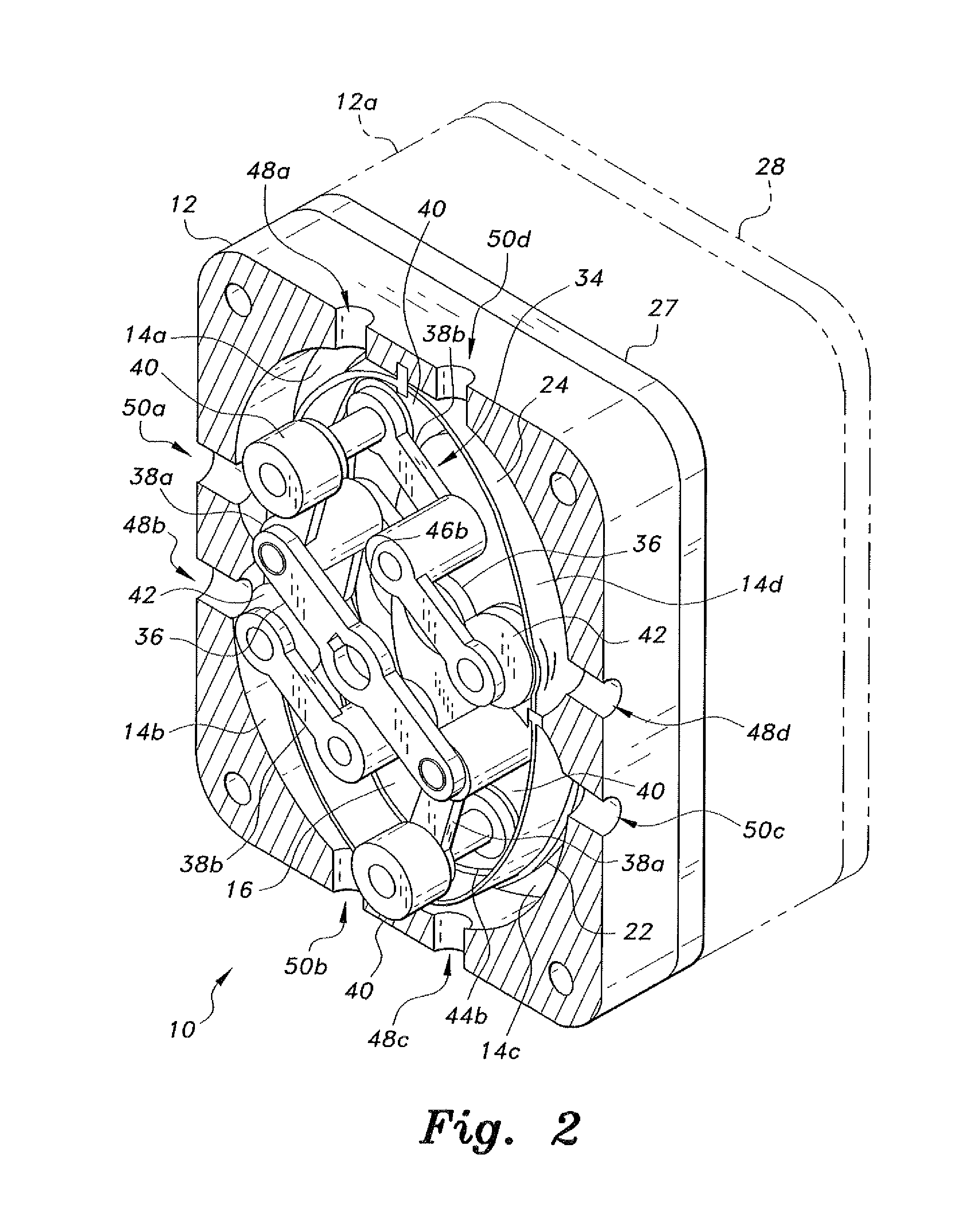
[0020]The rotary diaphragm pump has a case defining a plurality of chambers surrounding an elliptical core or cavity. A corresponding elliptical frame and diaphragm assembly is disposed within the case. The diaphragm is in the form of a closed band that forms an elliptical shape when stretched over its frame. A mechanism urges the band outward into the chambers to provide pumping action in each of the chambers. The resulting multiple strokes or pulses in each revolution of the mechanism provide a relatively smooth flow from the pump, while the elliptical band configuration of the diaphragm results in relatively low stresses on the diaphragm.

[0021]FIGS. 1 and 2 of the drawings show a first embodiment of the rotary diaphragm pump 10, illustrating its basic components. The pump 10 has a case 12 having four chambers 14a, 14b, 14c, and 14d (defined counterclockwise from the upper left chamber 14a) surrounding an elliptical central cavity or core 16. The case 12 has mutually opposed first...


PUM


Abstract

The rotary diaphragm pump has a flexible, resilient diaphragm band surrounding an elliptical frame within a case having four chambers surrounding an elliptical core. An articulating mechanism has a plurality of wheels traveling along the elliptical edges of the frame. The mechanism extends and retracts as the wheels move from maximum extension along the major axis of their elliptical tracks to minimum extension at the minor axis of their tracks. This mechanism drives a pair of actuator rollers along the inner surface of the diaphragm, periodically forcing the diaphragm into the surrounding chambers to produce the pumping action. Each chamber has an inlet port and an outlet port. The various ports may be interconnected to provide one or more multi-stage pumps in combination with one or more single-stage pumps, as desired. Two or more pumps may be joined in tandem to provide greater capacity from a single drive shaft.

Description

BACKGROUND OF THE INVENTION[0001]1. Field of the Invention[0002]The present invention relates generally to fluid transfer devices, and particularly to a rotary diaphragm pump having an elliptical band diaphragm driven by an articulating roller assembly.[0003]2. Description of the Related Art[0004]Fluid transfer devices, e.g., pumps, often use the principle of a distensible elastomeric diaphragm as the primary component therein. Various mechanisms are used to move the diaphragm and thereby change the volume of one or more chambers within the pump in order to move a fluid (air or liquid) through the pump. The diaphragm in such a pump generally has a flat, planar configuration when it is not distended by the drive mechanism. The diaphragm in such a pump configuration is secured about its periphery, and the drive mechanism generally is secured to the central area of the diaphragm. The stress imposed upon the diaphragm by being mechanically attached to other structure both about its peri...

Claims


Application Information

Patent Timeline
Patent Type & Authority Applications(United States)
IPC IPC(8): F04C5/00
CPCF04B43/1253F04C5/00
Inventor AL-HAWAJ, OSAMA M.
Owner KUWAIT UNIV
Features
  • R&D
  • Intellectual Property
  • Life Sciences
  • Materials
  • Tech Scout
  • Unparalleled Data Quality
  • Higher Quality Content
  • 60% Fewer Hallucinations
Learn More