
Airbag connector system

a connector system and airbag technology, applied in the direction of connection, electrical apparatus, coupling device connection, etc., can solve the problems of undesirable use of cpa member, unable to detect the mated state of both plug connectors to squib sockets, and both plug connectors lack the possibility of visibly detecting the mated state of plug connectors, etc., to increase the resistance to further movement, increase the bias of the latching arm, and increase the deflection

Active Publication Date: 2014-02-13
APTIV TECH LTD
View PDF2 Cites 15 Cited by
  • Summary
  • Abstract
  • Description
  • Claims
  • Application Information

AI Technical Summary

Benefits of technology

The patent describes a connector system that includes a deflection portion that causes the latching arm to bend when the plug connector is mounted with the retainer. This deflection makes it harder for the plug connector to move any further and ensures a secure connection. The system also includes a mechanism that prevents the connection from being made until the plug connector is fully inserted, making sure that the connectors are properly mated. This helps to visually indicate to the operator that the connectors are fully connected and both mechanically and electrically connected.

Problems solved by technology

Even though the solution as proposed in the EP '591 works satisfactory, for certain applications the use of a CPA member is undesirable for example because of space limitations.
Even though the latter two plug connectors are provided with reliable locking mechanisms and can be connected to squib sockets without CPA members, both plug connectors lack the possibility to visibly detect the mated state of the plug connectors to squib sockets.

Method used


Image

  • Airbag connector system
  • Airbag connector system
  • Airbag connector system

Examples


Embodiment Construction

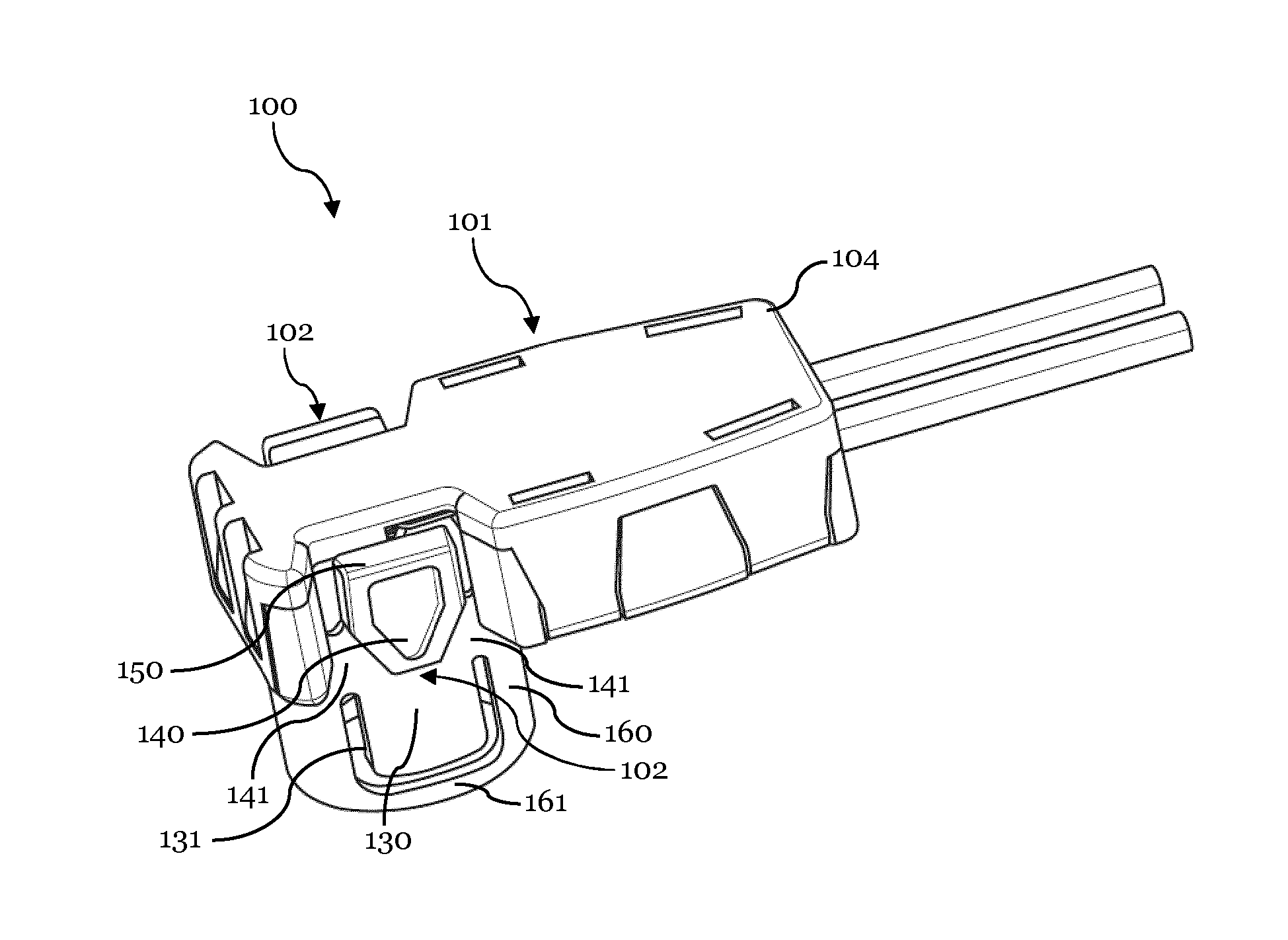
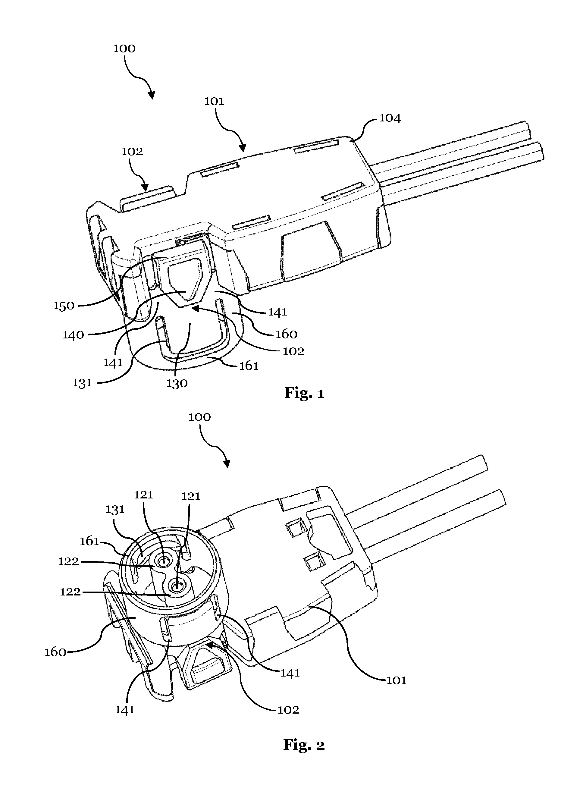
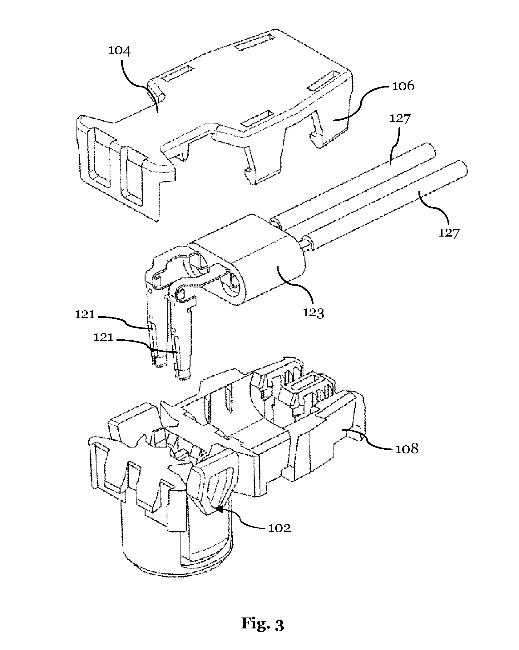
[0036]FIG. 1 shows a plug connector 100 to be used in connection with an airbag connector system. The plug connector 100 is provided with a connector housing 101 which is closed by a lid 104. The connector housing 101 is provided with a connection tube 160 with a safety ring 161. The plug connector 100 is further provided with two latching arms 102 which are formed integrally with the connection tube 160. Latching sections 130 of the latching arms 102, which are provided with inwardly directed latching projections 131 (see also FIG. 2), are cut out of the connection tube 160. The latching arms 102 are connected to the connection tube 160 via flexible portions (connection bridges) 141 which are parts of intermediate portions of the latching arms 102. Further, the latching arms 102 are provided with release members 150 which can be pressed inwardly towards the connector housing 101 such that the latching arms 102 can be pivoted around pivot members 140, i.e. around said intermediate p...


PUM


Abstract

The present invention relates to a connector system comprising a plug connector and a retainer configured to be inserted into a corresponding holder. The plug connector comprises a connector housing and a latching arm assigned to the connectorhousing, whereby the plug connector is configured to be mountable with the retainer. The connector system comprises a deflection portion for causing the latching arm to deflect upon mounting of the plug connector with the retainer. The deflection portion is shaped such that the deflection provides increasing resistance against further movement of the plug connector. The connector system further comprises a release portion configured to enable a release deflection of the latching arm. The release portion is shaped so the release deflection does not provide resistance against further movement of the plug connector. Still further, the connector system comprises a latching portion configured to allow the latching arm to lock the plug connector.

Description

CROSS-REFERENCE TO RELATED APPLICATION[0001]This application is a national stage application under 35 U.S.C. §371 of PCT Application Number PCT / EP2012 / 057412 having an international filing date of Apr. 23, 2012 which designated the United States, which PCT application claimed the benefit of PCT Application Number PCT / IB2011 / 001219, filed Apr. 22, 2011, the entire disclosure of each of which are hereby incorporated herein by reference.TECHNICAL FIELD OF THE INVENTION[0002]The present invention relates to a connector system comprising a plug connector and a retainer, both configured to be connected to a corresponding socket, whereby an electrical connection between the plug connector and the socket can be established only when the connector system is correctly assembled.BACKGROUND OF THE INVENTION[0003]In many fields of applications it is important that save coupling between connectors and corresponding counter connectors can be guaranteed. In particular in the case of automotive safe...

Claims


Application Information

Patent Timeline
Patent Type & Authority Applications(United States)
IPC IPC(8): H01R13/627
CPCH01R13/6275H01R13/6273H01R13/627H01R13/6272
Inventor GUNREBEN, MICHAELREGNIER, VINCENT
Owner APTIV TECH LTD
Learn More