Control device

a control device and control technology, applied in the direction of electric devices, engine-driven generators, transportation and packaging, etc., can solve the problems of shock to the occupants of the vehicle, torque difference may be caused, etc., to reduce torque, suppress an uncomfortable feeling, and reduce torque. the effect of necessary

Active Publication Date: 2014-02-13
AISIN AW CO LTD
View PDF5 Cites 10 Cited by
  • Summary
  • Abstract
  • Description
  • Claims
  • Application Information

AI Technical Summary

Benefits of technology

[0031]According to the configuration, the hydraulic pressure supplied to the second friction engagement device during the hydraulic pressure regulation control can be decided appropriately on the basis of the target transfer torque capacity for the second friction engagement device which is decided on the basis of torque necessary to cause the rotational state of the rotary electric machine during the rotational state control to coincide with the target rotational state. By deciding the target transfer torque capacity for the second friction engagement device as in the configuration, in addition, it is possible to gradually reduce torque necessary to cause the rotational state of the rotary electric machine to coincide with the target rotational state. That is, the output torque of the rotary electric machine produced during the rotational state control can be caused to approach the predetermined torque produced afte

Problems solved by technology

Therefore, in the case where there is an error in transfer torque capacity of the first friction engagement device, a torque difference may be caused in torque transferred to the wheels via the second friction engagement device when the second friction engagement device is brought from the slip engagement state into the direct engagement state and the rotational speed feedback control for the rotary electric machine is terminated to start torque control for the rotary electric machine.
This may cause occupants of the vehicle to feel a shock.
Such an issue

Method used


Image

  • Control device
  • Control device
  • Control device

Examples


Embodiment Construction

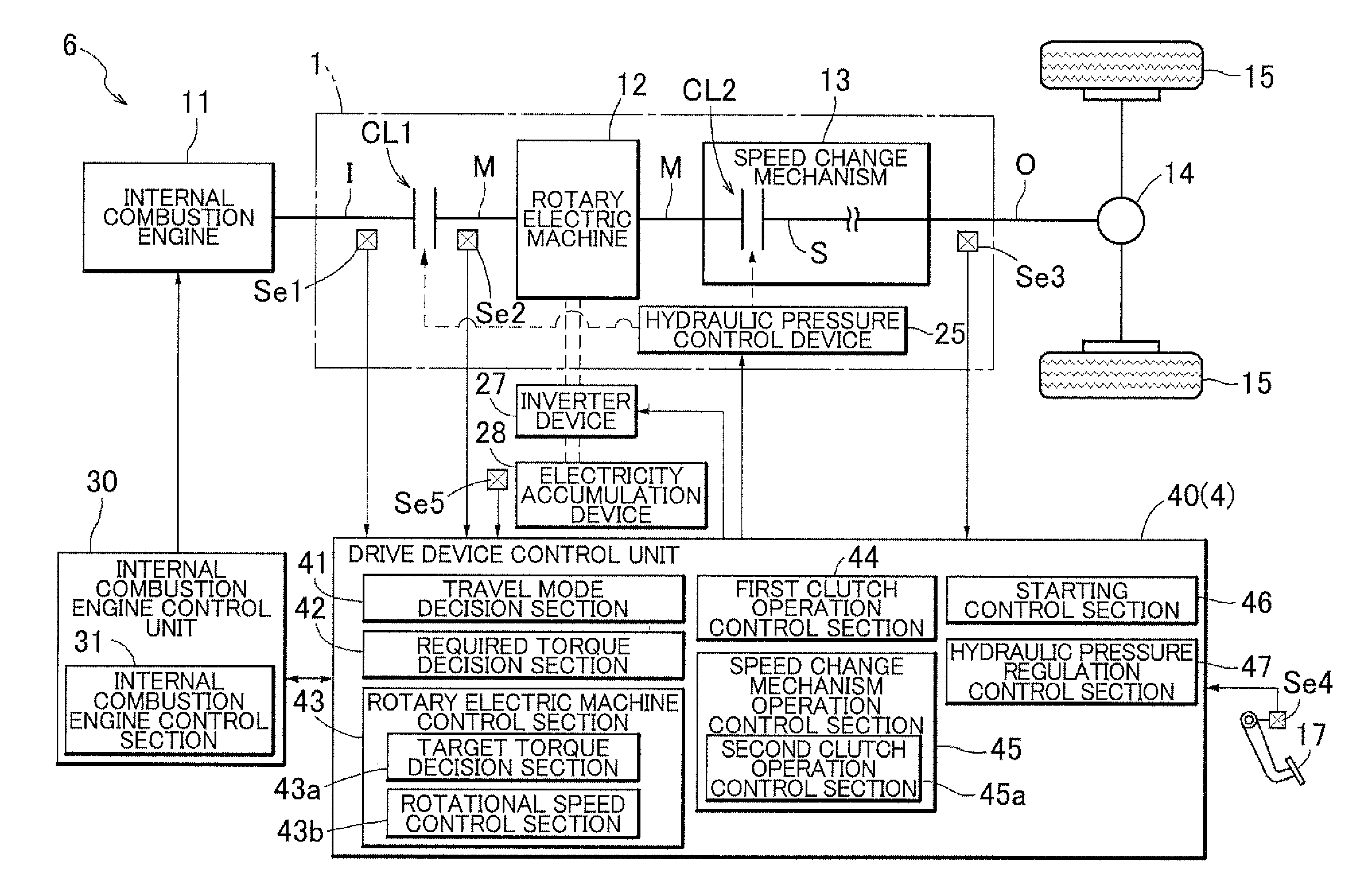
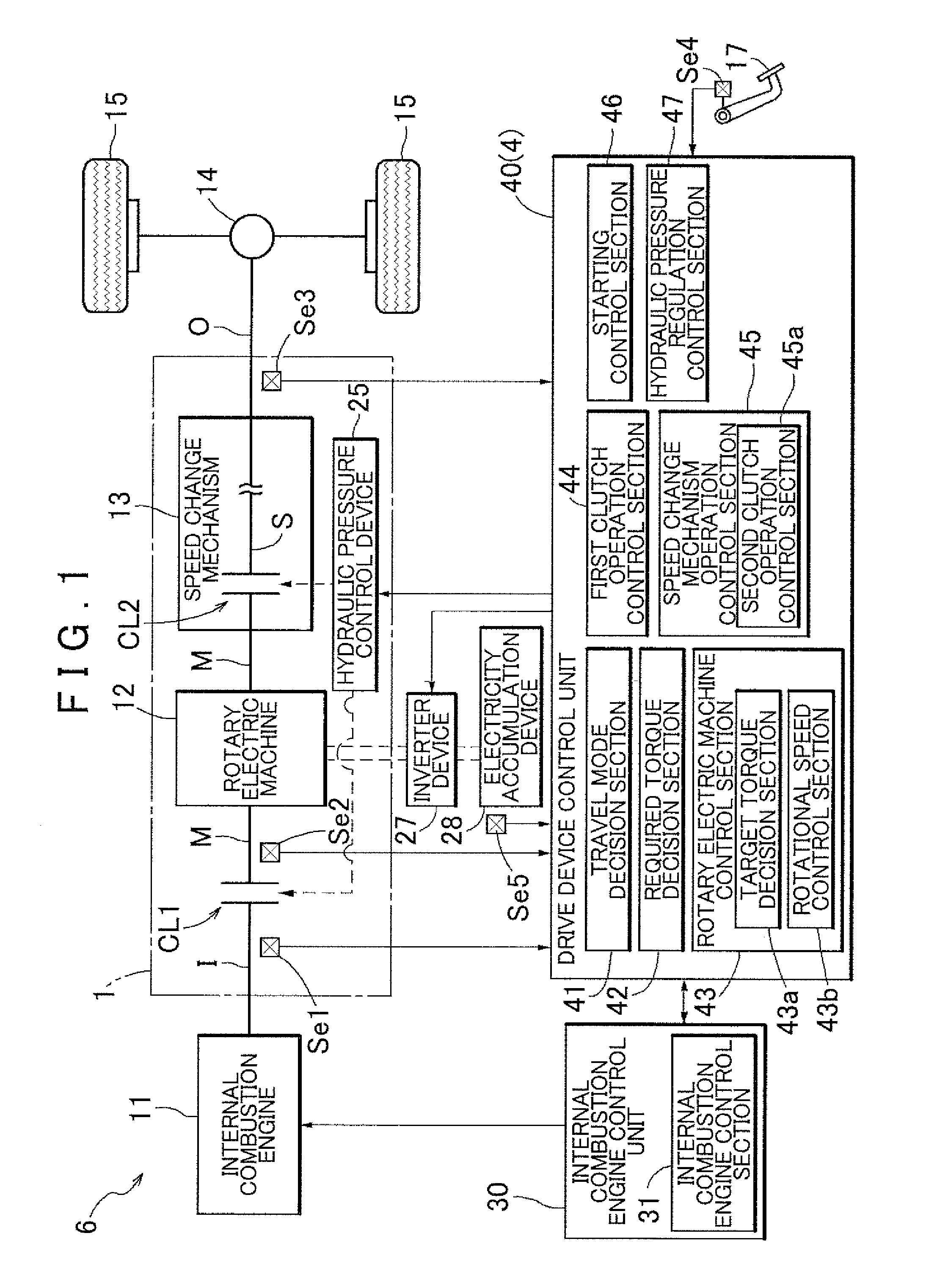
[0038]A control device according to an embodiment of the present invention will be described with reference to the drawings. As shown in FIG. 1, a control device 4 according to the embodiment is a drive device control unit that controls a drive device 1. Here, the drive device 1 according to the embodiment is a vehicle drive device (hybrid vehicle drive device) that drives a vehicle (hybrid vehicle) 6 that includes both an internal combustion engine 11 and a rotary electric machine 12 as drive force sources for wheels 15. The control device 4 according to the embodiment will be described in detail below.

[0039]In the following description, the term “drivably coupled” means a state in which two rotary elements are coupled to each other in such a way that allows transfer of a drive force, which includes a state in which the two rotary elements are coupled to each other to rotate together with each other, and a state in which the two rotary elements are coupled to each other via one or ...


PUM


Abstract

The present invention relates to a control device that controls a vehicle drive device in which a rotary electric machine is provided in a power transfer path that connects between an internal combustion engine and wheels and in which a first friction engagement device is provided between the internal combustion engine and the rotary electric machine and a second friction engagement device is provided between the rotary electric machine and the wheels.

Description

INCORPORATION BY REFERENCE[0001]The disclosure of Japanese Patent Application No. 2011-157992 filed on Jul. 19, 2011, Japanese Patent Application No. 2011-150169 filed on Jul. 6, 2011, Japanese Patent Application No. 2012-013257 filed on Jan. 25, 2012 including the specification, drawings and abstract is incorporated herein by reference in its entirety.BACKGROUND OF THE INVENTION[0002]The present invention relates to a control device that controls a vehicle drive device in which a rotary electric machine is provided in a power transfer path that connects between an internal combustion engine and wheels and in which a first friction engagement device is provided between the internal combustion engine and the rotary electric machine and a second friction engagement device is provided between the rotary electric machine and the wheels.DESCRIPTION OF THE RELATED ART[0003]A device described in Japanese Patent Application Publication No. 2010-149640 (JP 2010-149640 A) is already known as ...

Claims


Application Information

Patent Timeline
IPC IPC(8): B60W20/00B60L50/16
CPCY10S903/93B60W20/10B60L50/16B60K6/48B60L3/00B60L15/20B60W10/02B60W10/06B60W10/08B60W20/40B60K2006/4825B60L2270/145B60L2240/507B60L2240/441B60L2240/443B60L2240/421B60L2240/423B60L2260/26B60L2210/40B60W2710/025B60W2710/083B60W2710/081B60W2510/083B60W2510/081B60W2510/0657B60W2050/0008B60W20/00B60W2710/023B60W2710/027B60W20/20B60L15/2054B60Y2300/429B60K6/547Y02T10/72Y02T10/62Y02T10/64Y02T10/7072Y02T10/70
Inventor YOSHIDA, TAKASHIHAKUMURA, YOMEITAJIMA, YOICHIKAWAI, HIDEYA
Owner AISIN AW CO LTD
Why Eureka
Try Eureka