
Cyclonic separator

Active Publication Date: 2014-02-20
DYSON TECH LTD
View PDF32 Cites 18 Cited by
  • Summary
  • Abstract
  • Description
  • Claims
  • Application Information

AI Technical Summary

Benefits of technology

This patent is about a new design for a cyclonic separator that improves its separation efficiency. Traditionally, fluid is introduced into the cyclone chamber through the outer wall, which causes dirt to pass through easily. However, this new design introduces fluid in a way that prevents this from happening. Instead, the fluid enters through the filter, which prevents the filter from collapsing and requires no additional support structure. This new design creates a net increase in separation efficiency.

Problems solved by technology

As a result, dirt smaller than the shroud perforations will pass immediately through the shroud, resulting in a drop in separation efficiency.

Method used


Image

  • Cyclonic separator
  • Cyclonic separator
  • Cyclonic separator

Examples


Embodiment Construction

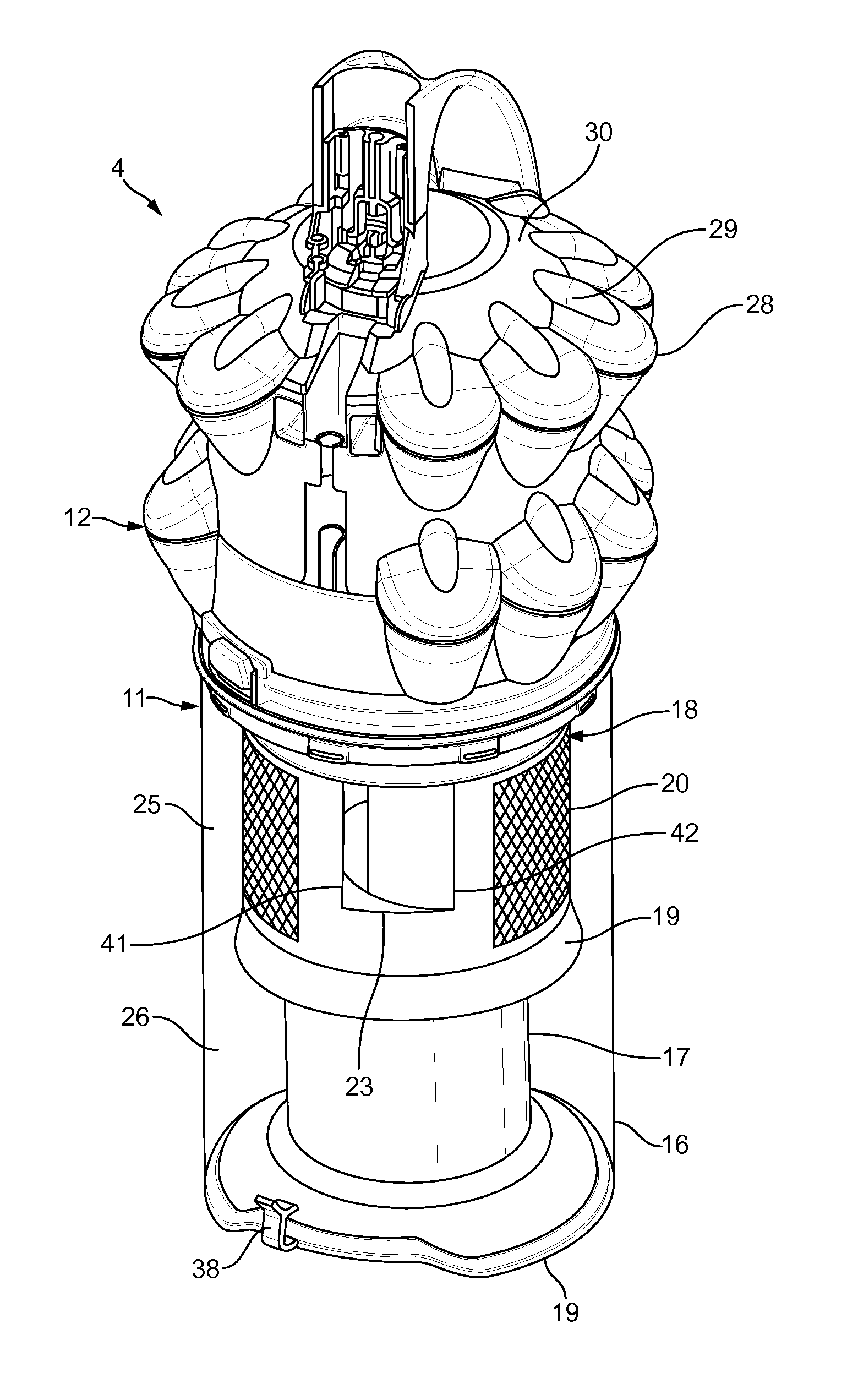
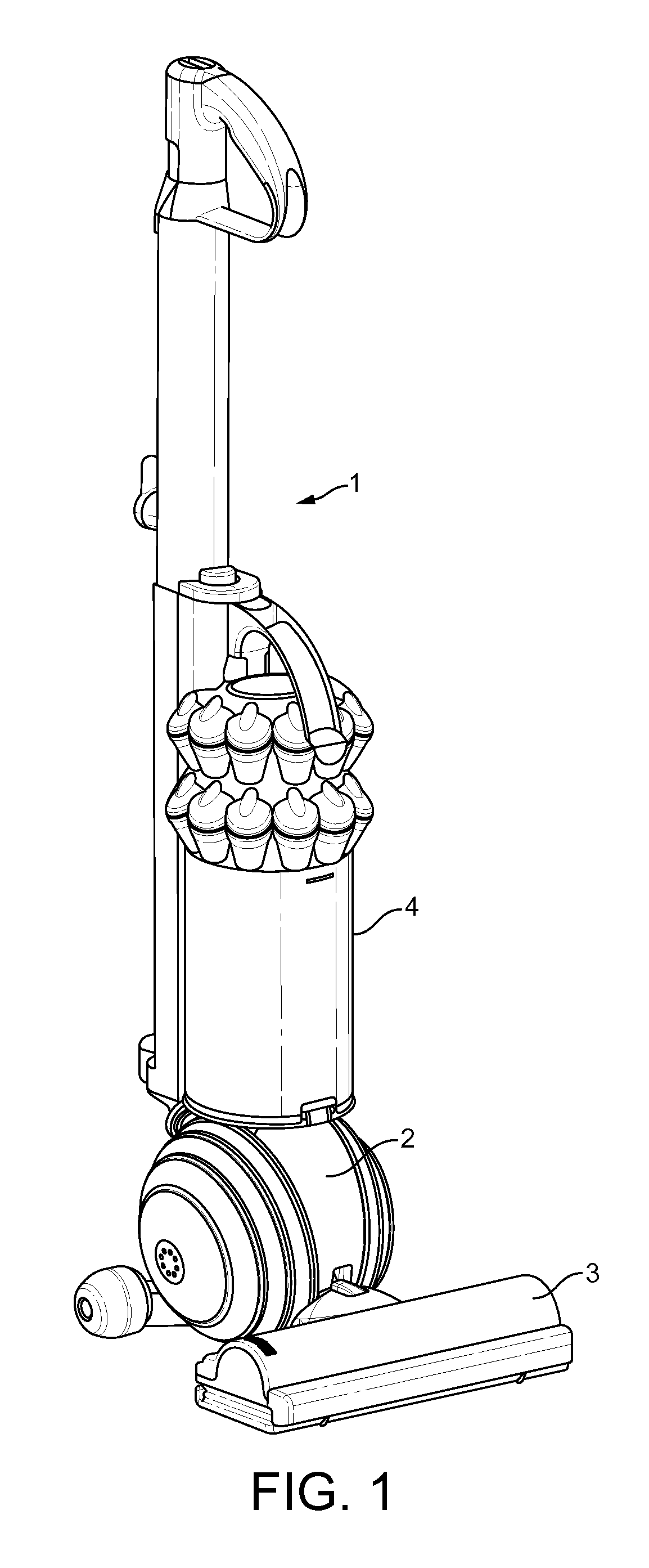
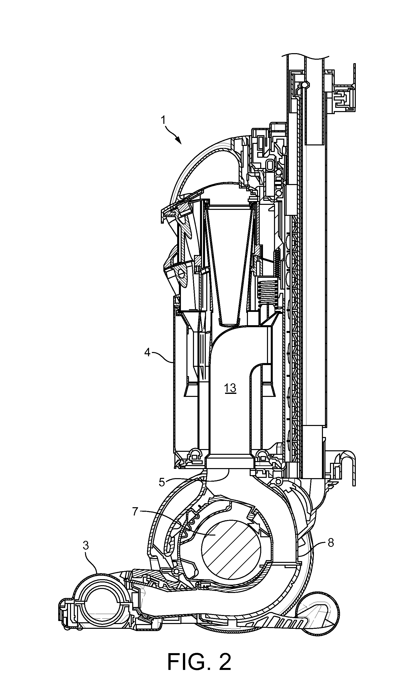
[0033]The upright vacuum cleaner 1 of FIGS. 1 to 3 comprises a main body 2 to which are mounted a cleaner head 3 and a cyclonic separator 4. The cyclonic separator 4 is removable from the main body 2 such that dirt collected by the separator 4 may be emptied. The main body 2 comprises a suction source 7, upstream ducting 8 that extends between the cleaner head 3 and an inlet 5 of the cyclonic separator 4, and downstream ducting 9 that extends between an outlet 6 of the cyclonic separator 4 and the suction source 7. The suction source 7 is thus located downstream of the cyclonic separator 4, which in turn is located downstream of the cleaner head 3.

[0034]The suction source 7 is mounted within the main body 2 at a location below the cyclonic separator 4. Since the suction source 7 is often relatively heavy, locating the suction source 7 below the cyclonic separator 4 provides a relatively low centre of gravity for the vacuum cleaner 1. As a result, the stability of the vacuum cleaner ...


PUM

PropertyMeasurementUnit
Areaaaaaaaaaaa

Abstract

A cyclonic separator comprising a cyclone chamber defined between an outer wall and a shroud. The shroud comprises an inlet opening through which fluid enters the cyclone chamber, and a plurality of perforations through which fluid exits the cyclone chamber. Fluid within the cyclone chamber is then free to spiral about the shroud and over the inlet opening.

Description

REFERENCE TO RELATED APPLICATIONS[0001]This application is a national stage application under 35 USC 371 of International Application No. PCT / GB2012 / 050840, filed Apr. 16, 2012, which claims the priority of United Kingdom Application No. 1106454.0, filed Apr. 15, 2011, and United Kingdom Application No. 1106455.7, filed Apr. 15, 2011, the entire contents of which are incorporated herein by reference.FIELD OF THE INVENTION[0002]The present invention relates to a cyclonic separator and to a vacuum cleaner incorporating the same.BACKGROUND OF THE INVENTION[0003]Vacuum cleaners having a cyclonic separator are now well known. Efforts are continually being made to improve the separation efficiency of the separator.SUMMARY OF THE INVENTION[0004]In a first aspect, the present invention provides a cyclonic separator comprising a cyclone chamber defined between an outer wall and a shroud, the shroud comprising an inlet opening through which fluid enters the cyclone chamber, and a plurality of...

Claims


Application Information

Patent Timeline
IPC IPC(8): A47L9/16
CPCA47L9/1608A47L9/1641A47L9/1666A47L9/20B04C5/12B04C5/28B04C2009/004A47L9/165B04C5/04B04C5/185A47L9/16A47L9/1658
Inventor DYSON, JAMESCROUCH, JEREMY WILLIAMROBERTSON, JAMES SRUARTGAMMACK, PETER DAVIDIRELAND, SIMON EDWARD
Owner DYSON TECH LTD
Learn More