Tsru with inlet spray system configurations for distribution of solvent diluted tailings

a technology spray system, which is applied in the direction of hydrocarbon oil dewatering/demulsification, charging-discharging device combination, separation process, etc., can solve the problem that the amount of solvent recovered from the same feed flow is not proportionate to the amount of solvent recovered, and the cost and environmental impact preclude direct discharging of solvent diluted tailings. problem, to achieve the effect of facilitating the choked flow

Inactive Publication Date: 2014-02-20
TRUENORTH ENERGY CORP
View PDF5 Cites 14 Cited by
  • Summary
  • Abstract
  • Description
  • Claims
  • Application Information

AI Technical Summary

Benefits of technology

The invention has a feature that allows for smooth airflow through its narrowest point (the throat). This helps improve performance by ensuring optimal gas exchange during use.

Problems solved by technology

The technical problem addressed in this patent text relates to improving the efficiency and effectiveness of processing used in extracting bitumen from oil sand. More specifically, the challenge includes reducing costs related to energy usage, equipment wear and tear, and negative impacts caused by solids buildup in the system. Various methods have been developed but they face common difficulties like poor fluidity control, limited space availability, and difficulty in removing dissolved solvents without causing fouling. There is therefore a need for new technology to overcome these challenges and achieve improved operational efficiencies.

Method used


Image

  • Tsru with inlet spray system configurations for distribution of solvent diluted tailings
  • Tsru with inlet spray system configurations for distribution of solvent diluted tailings
  • Tsru with inlet spray system configurations for distribution of solvent diluted tailings

Examples


Embodiment Construction

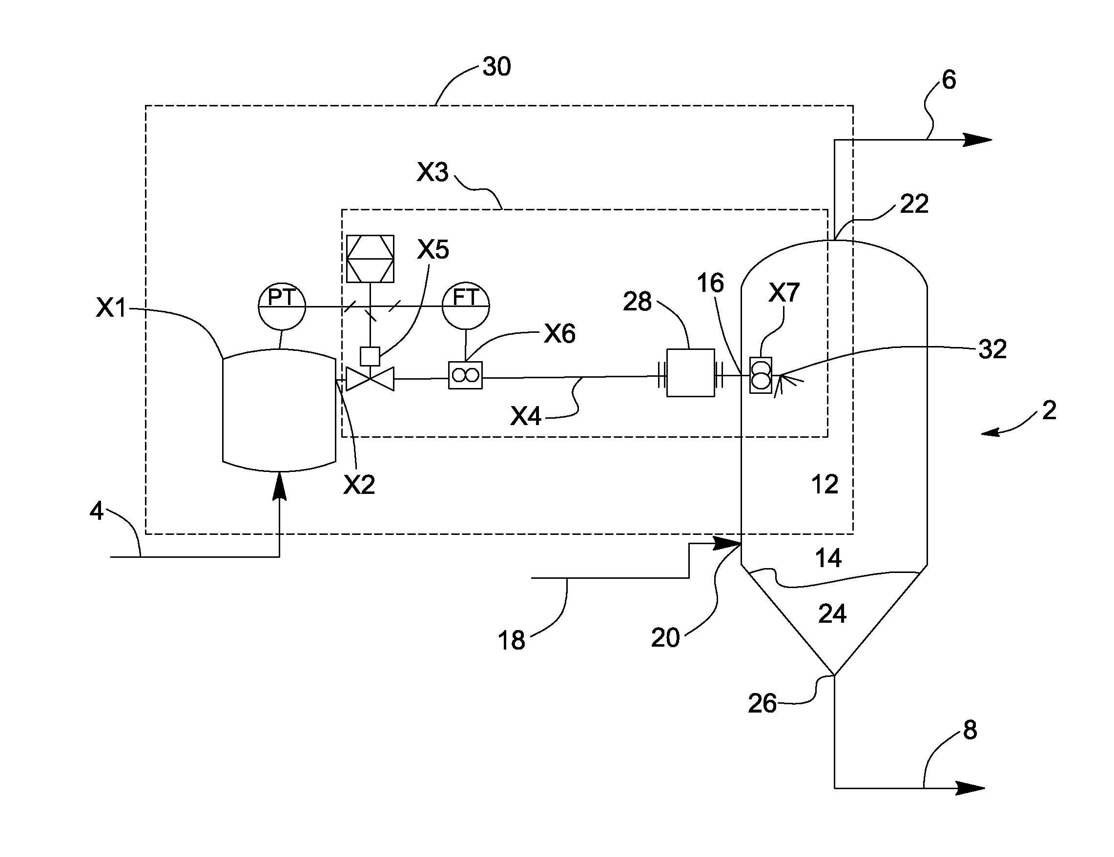
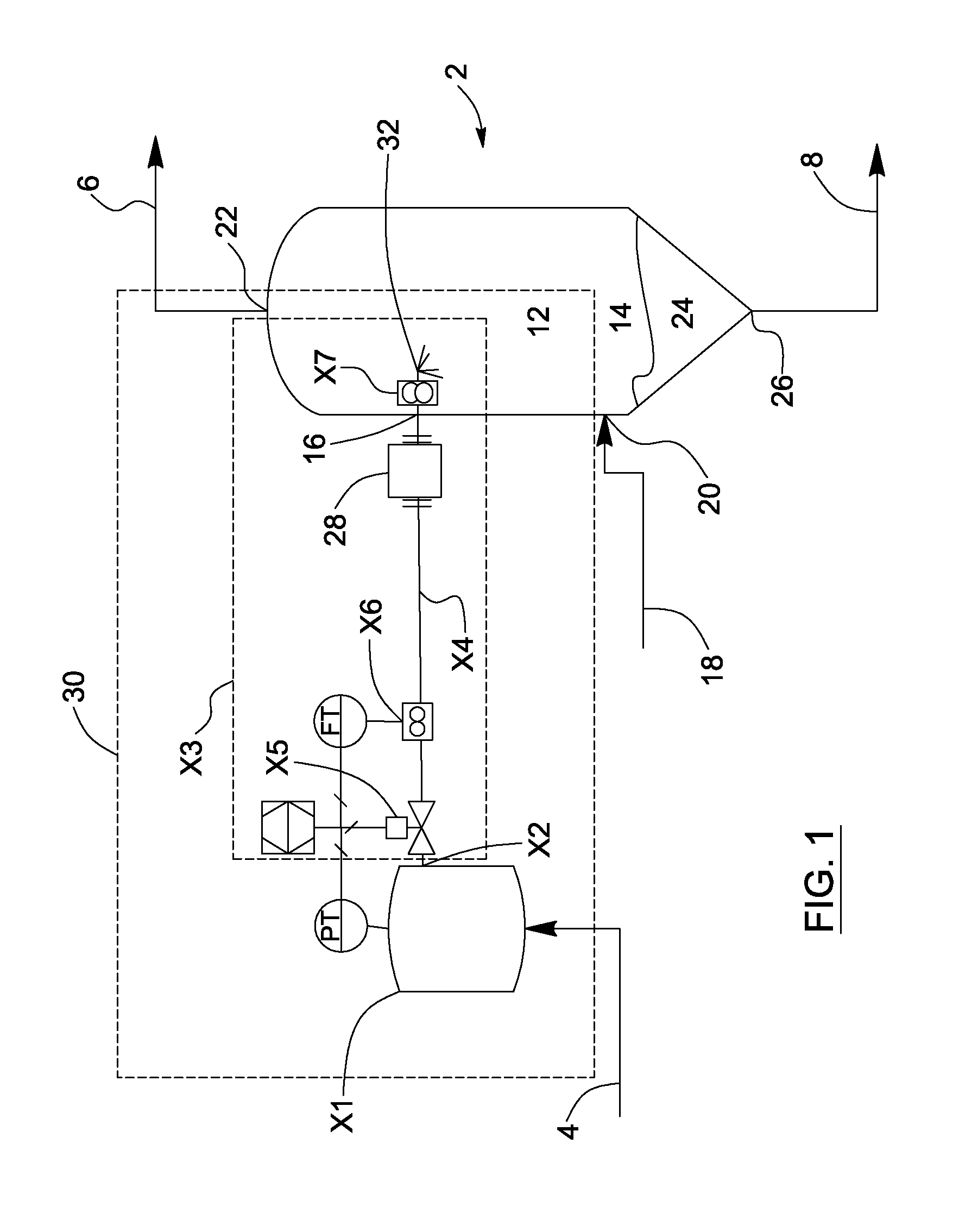
[0138]The present invention provides a tailings solvent recovery unit (TSRU) and a related process for recovering a solvent from solvent diluted tailings.

[0139]Referring to FIGS. 1 and 6, the TSRU comprises a separation apparatus (2), which may be a flashing apparatus or preferably a stripping apparatus, for receiving the solvent diluted tailings (4) (which are also referred to herein as solvent diluted tailings and froth treatment tailings) and separate it into two streams: a solvent component (6) and a stripped solvent recovered tailings component (8). The separation apparatus (2) preferably comprises a stripping vessel (2) with a stripping section (12) and a bottom section (14). The solvent diluted tailings (4) are fed to at least one tailings inlet (16) in fluid connection with the stripping section (12) where the stripping occurs by action of a stripping fluid (18) fed to the stripping vessel (2) through a stripping fluid inlet (20) located above the bottom section (14). The st...


PUM


Abstract

A tailings solvent recovery unit (TSRU) recovers a solvent from a solvent diluted tailings and includes a separation apparatus which has a flash vessel, tailings outlet, solvent outlet and an inlet spray system for supplying the diluted tailings to the flash vessel. The spray nozzle system may include multiple nozzles arranged around the periphery of the flash vessel for flash-atomization over its cross-section of the flashing chamber, a nozzle sized and configured to provide choked flow of the diluted tailings, multiple nozzles each being operable in an on/off mode to regulate a total feed flow, or multiple nozzles associated with a distributor and multiple feed conduits.

Description


Claims


Application Information

Patent Timeline
Owner TRUENORTH ENERGY CORP
Why Eureka
Try Eureka