
Water delivery and distribution pipeline system of standing reactive compensator thyristor velve set

A pipeline system and thyristor valve technology, applied in the direction of electric solid devices, semiconductor devices, semiconductor/solid device components, etc., can solve problems such as insulation breakdown, high leakage current insulation breakdown, and unbalanced flow ratio. To achieve the effect of ensuring automatic removal, reasonable system structure and meeting the requirements of use

Active Publication Date:
View PDF0 Cites 15 Cited by
  • Summary
  • Abstract
  • Description
  • Claims
  • Application Information

AI Technical Summary

Problems solved by technology

[0003] In the existing water transmission and distribution pipeline system, due to insufficient research on the insulation performance, chemical performance, and mechanical performance of pure water transmission pipeline materials in high-voltage environments, some materials such as ABS or PVC are used, resulting in aging, The leakage problem under continuous high temperature and high pressure conditions affects the normal heat dissipation of the device and even leads to accidents
At the same time, due to the unreasonable structure of the pipeline system, there are also problems of over-temperature and insulation breakdown due to unbalanced excess flow ratio and unsmooth exhaust of the pipeline system.
[0004] There will be a high potential difference between the devices and between the valve body layers. This potential difference directly acts on the two ends of the insulated water distribution pipe and the water column in the pipe. If the insulation strength of this section of the pipe is insufficient, it may cause excessive leakage current or even insulation shock. Put on

Method used


Image

  • Water delivery and distribution pipeline system of standing reactive compensator thyristor velve set
  • Water delivery and distribution pipeline system of standing reactive compensator thyristor velve set
  • Water delivery and distribution pipeline system of standing reactive compensator thyristor velve set

Examples


Embodiment Construction

[0039] Referring to accompanying drawing, the technical scheme that the present invention solves its technical problem to take includes the following contents:

[0040] 1) Calculation of the leakage current of the waterway

[0041] The leakage current of the insulated water distribution channel includes the leakage current of the fluid medium and the leakage current of the pipeline. The calculation of the leakage current of the pipeline is one of the main basis for the selection of pipeline materials and specifications, and it is also one of the main parameters of the electrical design of the valve group.

[0042] I=UA / σL

[0043] I is the leakage current in mA,

[0044] σ is the volume resistivity, the unit is MΩ.cm,

[0045] U is the applied voltage in V,

[0046] A is the cross-sectional area, in cm 2

[0047] L is the length in cm.

[0048] Using the above formula for calculation, when the volume resistivity of the pipe material used is greater than 1×10 16 In the c...


PUM


Abstract

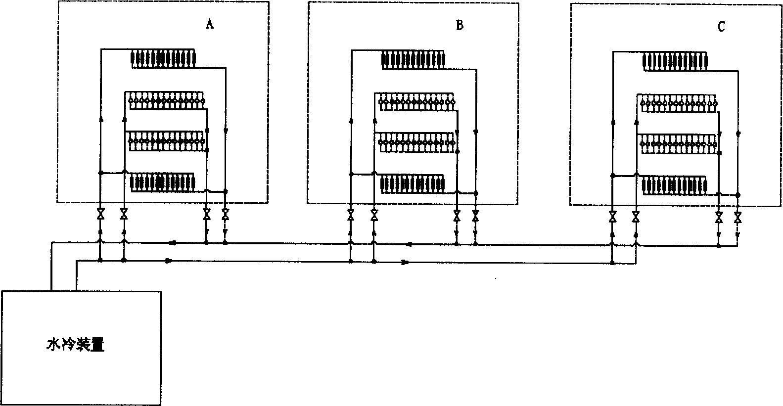
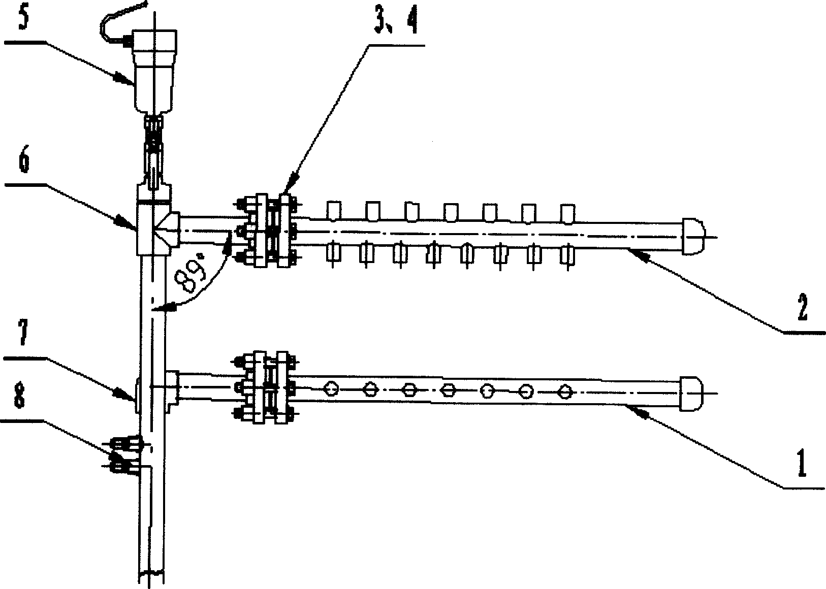
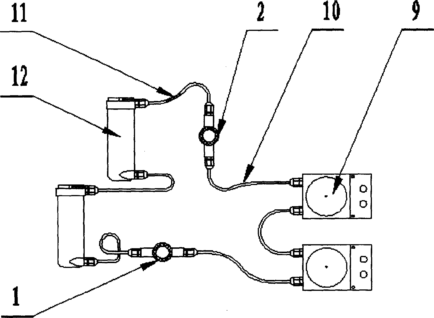
The invention is a thyristor valve group water feeding and distributing pipeline system for static reactive power compensator, where the valve group is divided into three phases, and the pipeline adopts a parallel connecting mode, and the flow of the three phases are balanced; the devices in the valve group are arranged and combined in grouped crimping form, the valve-group water feeding and distributing hose adopts a mode of connecting in series or in parallel. The invention arranges a water-distributing mother pipe as a water distributor, arranges flow choking element in the water distributing hose, arranges proper slope and auto gas exhaust valve on the pipeline, and arranges equipotential column at special design point of the insulating pipeline. The sealing ring has multiple sealing water veins, the sealing water veins closely fits the sealing surface of the flange to achieve multiple sealing protection effects. The system has reasonable structure, uniform flow distribution, equipotential pipeline design, and multiple measures for assuring sealing of cooling medium and automatic gas exhaust.

Description

technical field [0001] The invention relates to a thyristor valve of a static var compensator (SVC) in a power system and power electronic technology, in particular to a water transmission and distribution pipeline system of a thyristor valve group. Background technique [0002] With the application of high-voltage and high-power power electronic devices, especially the wide application of static var compensators with a voltage level of 35kV and below, the closed circulating water cooling system equipment using ultrapure water as the cooling medium is also widely used. The water transmission and distribution pipeline system of the thyristor valve group transports and distributes ultra-pure water with constant flow, pressure, conductivity, and temperature to each cooling unit: the water-cooled heat sink of the thyristor valve and the water-cooled pressure equalizing resistor, which circulate after sufficient heat exchange . At the same time, the water transmission and distri...

Claims


Application Information

Patent Timeline
IPC IPC(8): H01L23/473H05K7/20
Inventor 吴文伟卢志敏于坤山潘艳
Learn More