Check valve

a check valve and valve body technology, applied in the field of check valves, can solve the problems of complex and expensive valves, additional difficulty in repair damage, and additional difficulties, and achieve the effects of low friction, durable and reliable, and low cost of manufactur

Inactive Publication Date: 2007-03-01
TRANSPORTATION RES CORP
View PDF6 Cites 14 Cited by
  • Summary
  • Abstract
  • Description
  • Claims
  • Application Information

AI Technical Summary

Benefits of technology

[0013] The cavity that holds the flow blocking valve element is shaped such that the flow blocking valve element cannot become jammed but is always free to move in response to the flow through the valve. This is accomplished by ensuring that the contact points between the flow blocking valve element and the halves of the housing have low friction in the axial direction, and is sized so the flow blocking valve element cannot become wedged or jammed in the flow blocking plate cavit...

Problems solved by technology

The problem with current check valve technology is that the valves are complex and expensive.
Also, they may be constructed from a relatively large number of parts, and if the valve fails, pieces of the valve may be swept through the valve and into other parts of the system, causing further difficulties.
If the valve were to malfunction and break apart, pieces of t...

Method used


Image

  • Check valve
  • Check valve
  • Check valve

Examples


Embodiment Construction

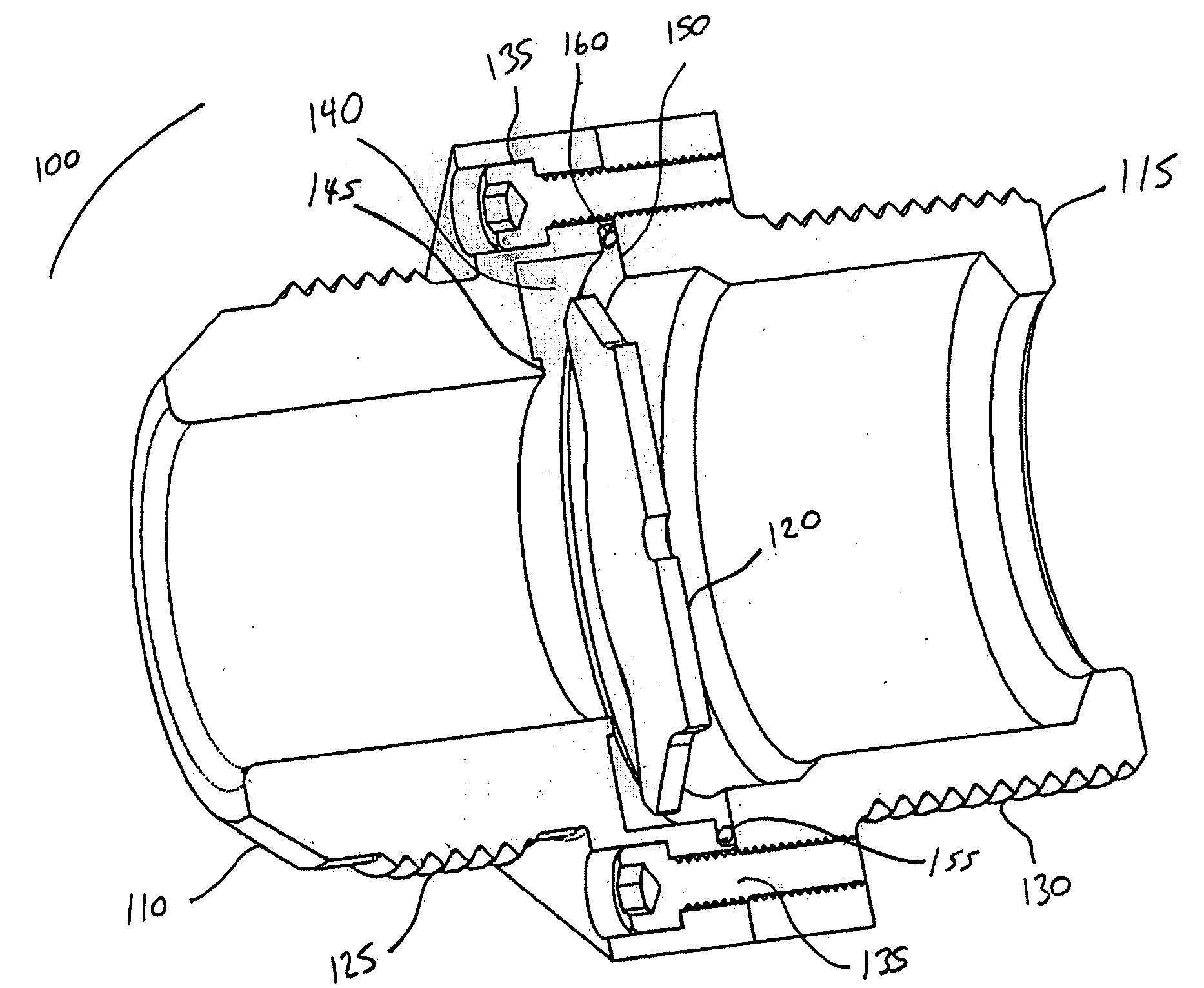
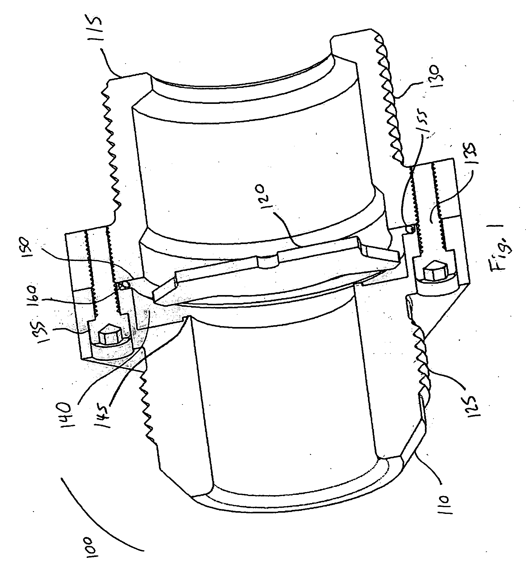
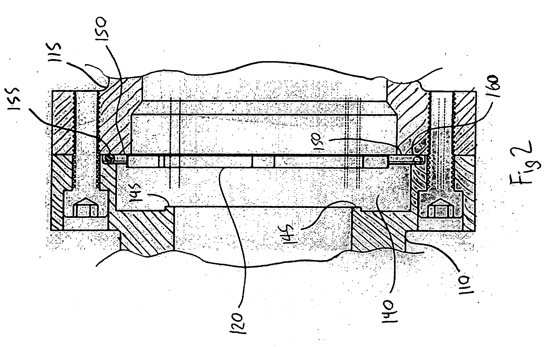
[0022]FIG. 1 is a pictorial cut-away view of the check valve of the present invention. As depicted, the check valve (100) includes an inlet-side housing (110), an outlet-side housing (115), a flow blocking valve element (120), inlet threads (125), outlet threads (130), two assembly bolts (135), a cylindrical valve element cavity (140), an inlet annular shoulder (145), an outlet annular shoulder (150), an O-ring cavity (155), and an O-ring (160). The flow blocking valve element (120) is unattached to the remainder of the assembly and is free to move about within the cylindrical valve element cavity depending on the flow of fluid in the valve at any instant. During operation in the non-inhibited flow direction, flow enters the valve on the inlet side, flows around the central disc of the flow blocking valve element (120) to the outlet side while the centering protrusions of the flow blocking valve element (120) rest on edges of the outlet annular shoulder (150). When the pressure on t...


PUM


Abstract

Described is a check valve with a housing having an inlet side and an outlet side, a flow blocking valve element with centering protrusions, an inlet annular shoulder, an outlet annular shoulder, cylindrical valve element cavity with an aspect ratio such that the flow blocking valve element cannot be put in a position where it is jammed. The centering protrusions on the flow blocking valve element support it on the outlet annular shoulder and allow flow to pass between the central disc of the valve element and the larger diameter of the outlet orifice. When flow is attempted in the inhibited direction, the flow blocking valve element is pressed against the inlet annular shoulder, forming a seal and blocking the flow. The valve has the advantage of being inexpensive to manufacture and highly reliable.

Description

BACKGROUND OF THE INVENTION [0001] 1. Field of the Invention [0002] The field of the invention is in check valves, valves that allow flow in one direction but not in the other. Particularly, the invention relates to check valves designed for low cost manufacturing and high reliability operation. [0003] 2. Description of Related Art [0004] Check valves are used when flow is needed in one direction in a system but must be blocked from the other direction. [0005] Check valves typically operate by blocking the flow of liquid with a movable flow-blocking element, such as a ball, a piston, or a plate, or a more complex valve element. [0006] The problem with current check valve technology is that the valves are complex and expensive. Also, they may be constructed from a relatively large number of parts, and if the valve fails, pieces of the valve may be swept through the valve and into other parts of the system, causing further difficulties. [0007] Particularly for applications such as a c...

Claims


Application Information

Patent Timeline
IPC IPC(8): F16K15/00
CPCF16K15/023Y10T137/7847Y10T137/7911
Inventor ASHURST, MARKMARTIN, THOMAS
Owner TRANSPORTATION RES CORP
Why Eureka
Try Eureka