Gas Gauge Compatible With Vacuum Environments

a technology of vacuum environment and gas gauge, applied in the direction of pressure difference measurement between multiple valves, instruments, printing, etc., can solve the problems of shorter wavelength light becoming absorbed by glass lenses, light not reaching silicon wafers, optical means of determining focus positioning are subject to errors

Inactive Publication Date: 2010-12-09
ASML HLDG NV
View PDF12 Cites 16 Cited by
  • Summary
  • Abstract
  • Description
  • Claims
  • Application Information

AI Technical Summary

Problems solved by technology

As chip manufacturers have been able to use shorter wavelengths of light, they have encountered a problem of the shorter wavelength light becoming absorbed by the glass lenses that are intended to focus the light.
Due to the absorption of the shorter wavelength light, the light fails to reach the silicon wafer.
However, optical means of determining focus positioning are subject to errors from interfering wave fronts from lower layers.
Firstly, since a typica

Method used


Image

  • Gas Gauge Compatible With Vacuum Environments
  • Gas Gauge Compatible With Vacuum Environments
  • Gas Gauge Compatible With Vacuum Environments

Examples


Embodiment Construction

[0026]While specific configurations and arrangements are discussed, it should be understood that this is done for illustrative purposes only. A person skilled in the pertinent art will recognize that other configurations and arrangements can be used without departing from the spirit and scope of the present invention. It will be apparent to a person skilled in the pertinent art that this invention can also be employed in a variety of other applications.

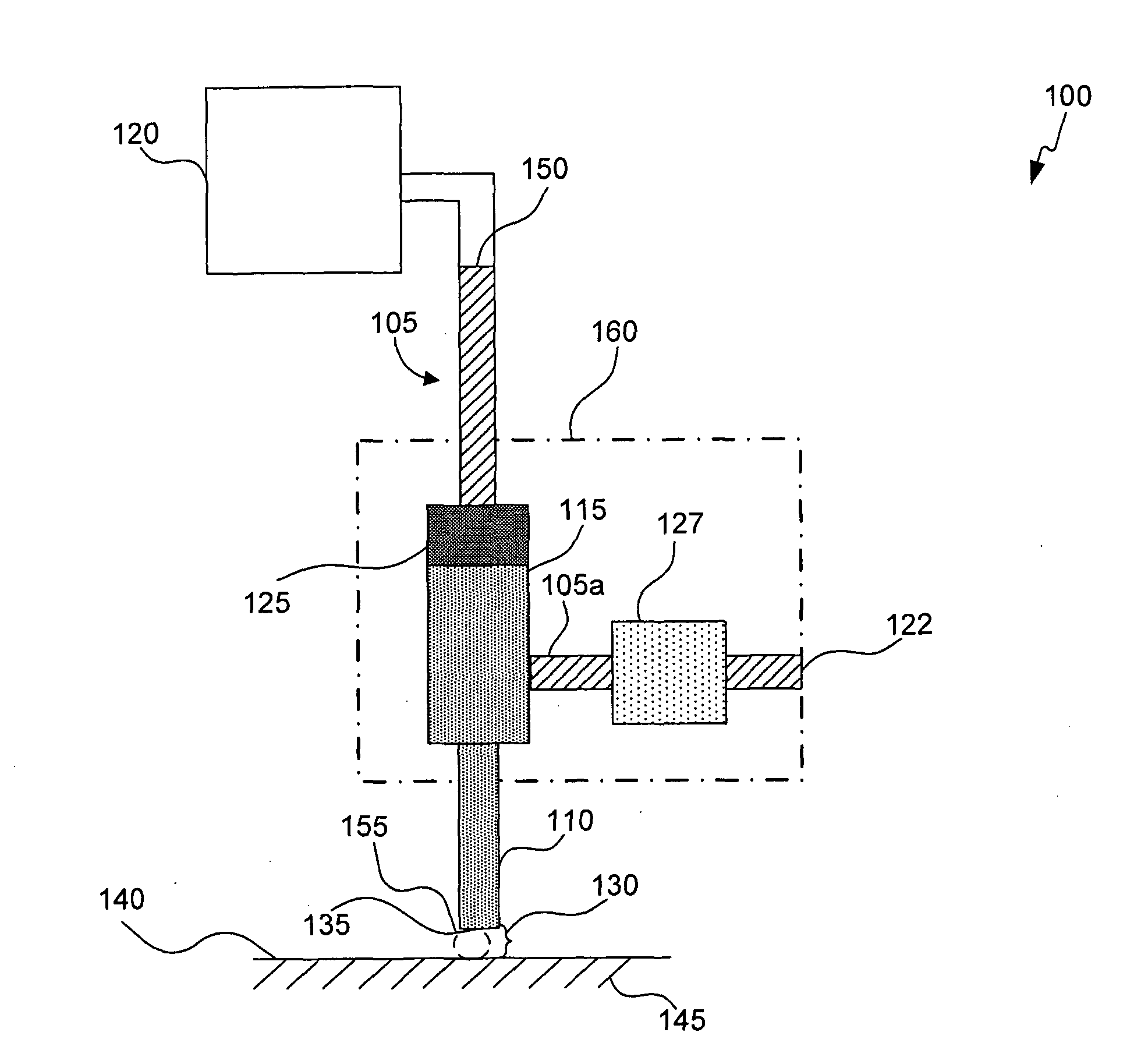
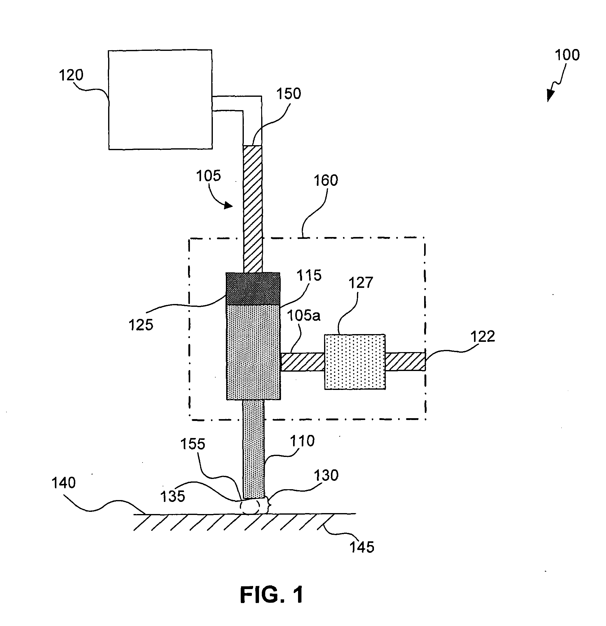
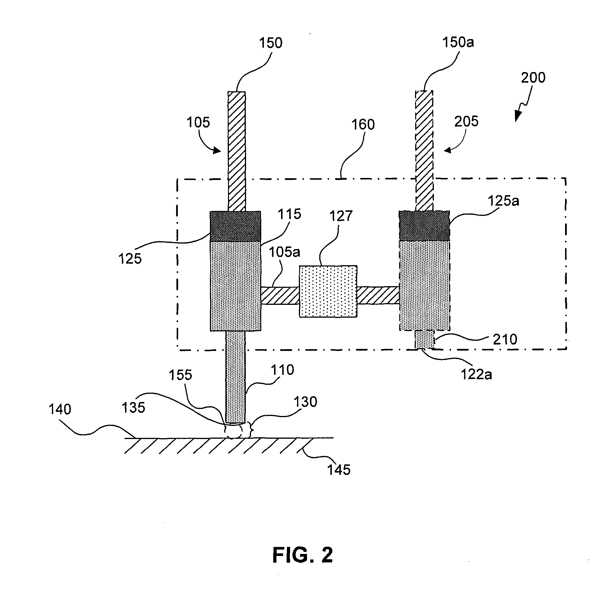
[0027]This specification discloses one or more embodiments that incorporate the features of the present invention involving gas gauges suitable for use in vacuum environments of a lithographic apparatus, for example, in Extreme Ultraviolet Lithography (EUVL) Systems. The disclosed embodiment(s) merely exemplify the invention. The scope of the invention is not limited to the disclosed embodiment(s). The invention is defined by the claims appended hereto.

[0028]The embodiment(s) described, and references in the specification to “one embo...


PUM


Abstract

A gas gauge (100) is provided for use in a vacuum environment having a measurement gas flow channel (105). The gas gauge comprises a measurement nozzle (110) in the measurement gas flow channel (105). The measurement nozzle (110) is configured to operate at a sonically choked flow condition of a volumetric flow being sourced from a gas supply (120) coupled to the measurement gas flow channel (105). The gas gauge (100) further comprises a pressure sensor (127) operatively coupled to the measurement gas flow channel (105) downstream from the sonically choked flow condition of the volumetric flow to measure a differential pressure of the volumetric flow for providing an indication of a gap (130) between a distal end of the measurement nozzle (135) and a target surface (140) proximal thereto.

Description

BACKGROUND[0001]1. Field of the Invention[0002]The present invention relates to the field of gas gauges suitable for use in vacuum environments of a lithographic apparatus.[0003]2. Related Art[0004]Lithography is a process used to create features on the surface of substrates. Such substrates can include those used in the manufacture of flat panel displays, circuit boards, various integrated circuits, and the like. A frequently used substrate for such applications is a semiconductor wafer. One skilled in the relevant art would recognize that the description herein would also apply to other types of substrates.[0005]During lithography, a wafer, which is disposed on a wafer stage (WS), is exposed to an image projected onto the surface of the wafer by an exposure system located within a lithography system. The exposure system includes a reticle (also called a mask) for projecting the image onto the wafer.[0006]The reticle is usually mounted on a reticle stage (RS) and generally located ...

Claims


Application Information

Patent Timeline
IPC IPC(8): G03B27/52G01N7/00
CPCG01B13/12G03F9/7026G01L13/02G03F9/7053G03F9/7096G03F9/7034
Inventor SCHULTZ, GEOFFREY ALAN
Owner ASML HLDG NV
Why Eureka
Try Eureka