Enhanced fuel injection based on choke flow rate

a fuel injection and flow rate technology, applied in the field of vehicle fuel systems, can solve the problems of difficult emission control, poor drivability, and no longer constant pressure of the fuel injector, and achieve the effect of minimizing the time for fuel tank emptying and maximizing the mass flow ra

Active Publication Date: 2014-10-23
FORD GLOBAL TECH LLC
View PDF12 Cites 15 Cited by
  • Summary
  • Abstract
  • Description
  • Claims
  • Application Information

AI Technical Summary

Benefits of technology

[0006]The inventors herein have discovered the problem with the above approaches and solved the problem. In particular, flow rate through the restriction is at a choked sonic flow where flow velocity in the choked region remains constant at sonic velocity. The inventors further recognized that sonic choke flow rate (in mass terms) continues to decrease as tank pressure decreases. The solution recognized by the inventors is to compute the sonic choke mass flow rate and control the average gaseous injection rate to be always below this value. Accurate control of gaseous fuel injection into the engine is then achievable because when the fuel injection rate is less than the sonically limited mass flow rate, pressure regulation occurs. In a further example, the inventors substantially maximized mass flow rate to the fuel injector to substantially minimize time for fuel tank emptying while maintaining on average mass flow rate from the fuel injector to be less than mass flow rate of gaseous fuel delivered to the fuel injector through the restriction, which in one embodiment may be located in the regulator, but in other embodiments can also be located in other locations within the fuel system. In another example, the inventors added the injection of a liquid fuel into the engine through a liquid fuel injector; and controlled the gaseous fuel injector and the liquid fuel injector to substantially achieve a desired engine operation—such as desired air / fuel control or desired torque control.

Problems solved by technology

A problem with motor vehicles operating on CNG is that as the tank nears empty, CNG supply to the engine fuel injector is no longer at constant pressure.
Consequently, accurate control of the amount of CNG delivered to the engine becomes difficult to control as the fuel tank empties resulting in poor drivability and difficult emission controls.
This type of approach results in frequent tank refills and limitation of the vehicle range of operation.

Method used


Image

  • Enhanced fuel injection based on choke flow rate
  • Enhanced fuel injection based on choke flow rate
  • Enhanced fuel injection based on choke flow rate

Examples


Embodiment Construction

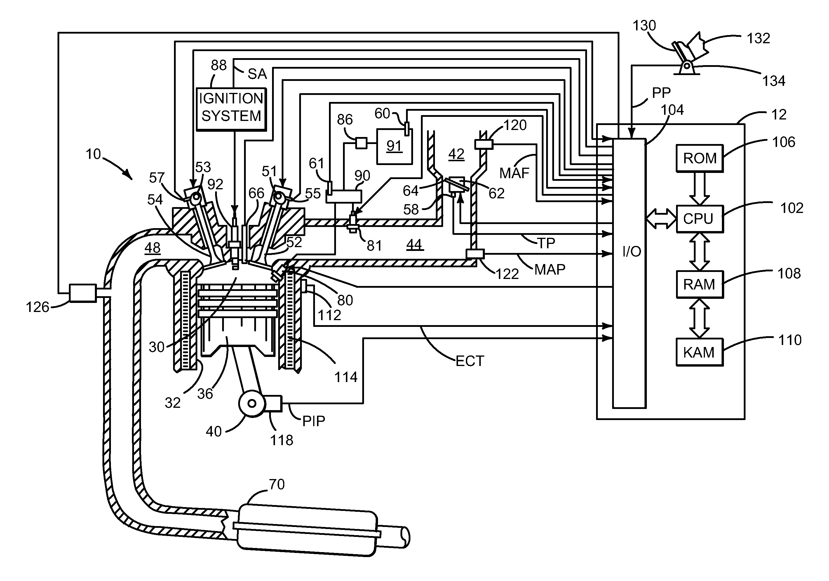
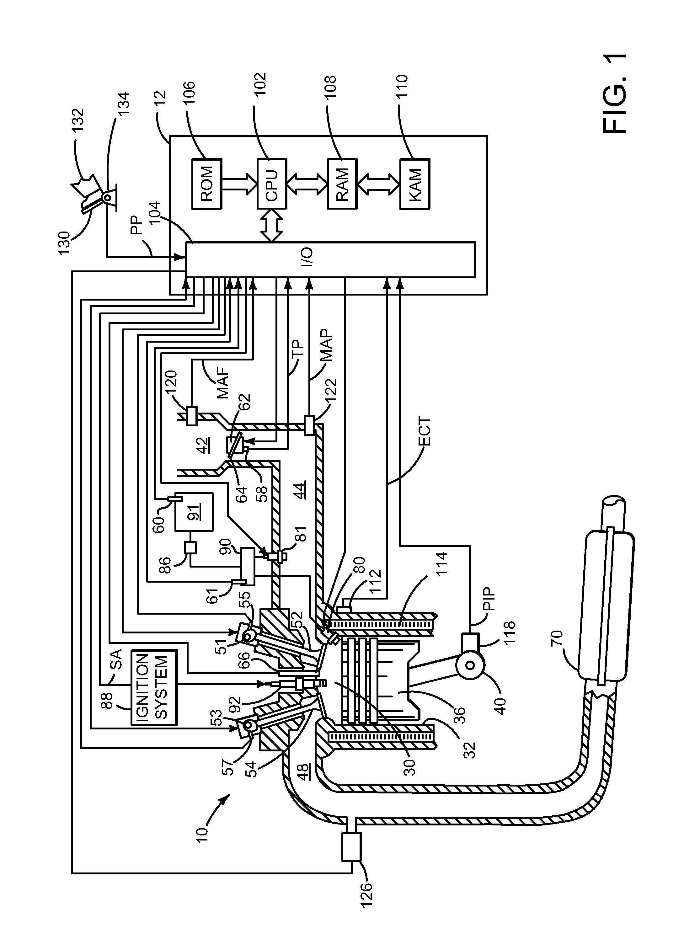
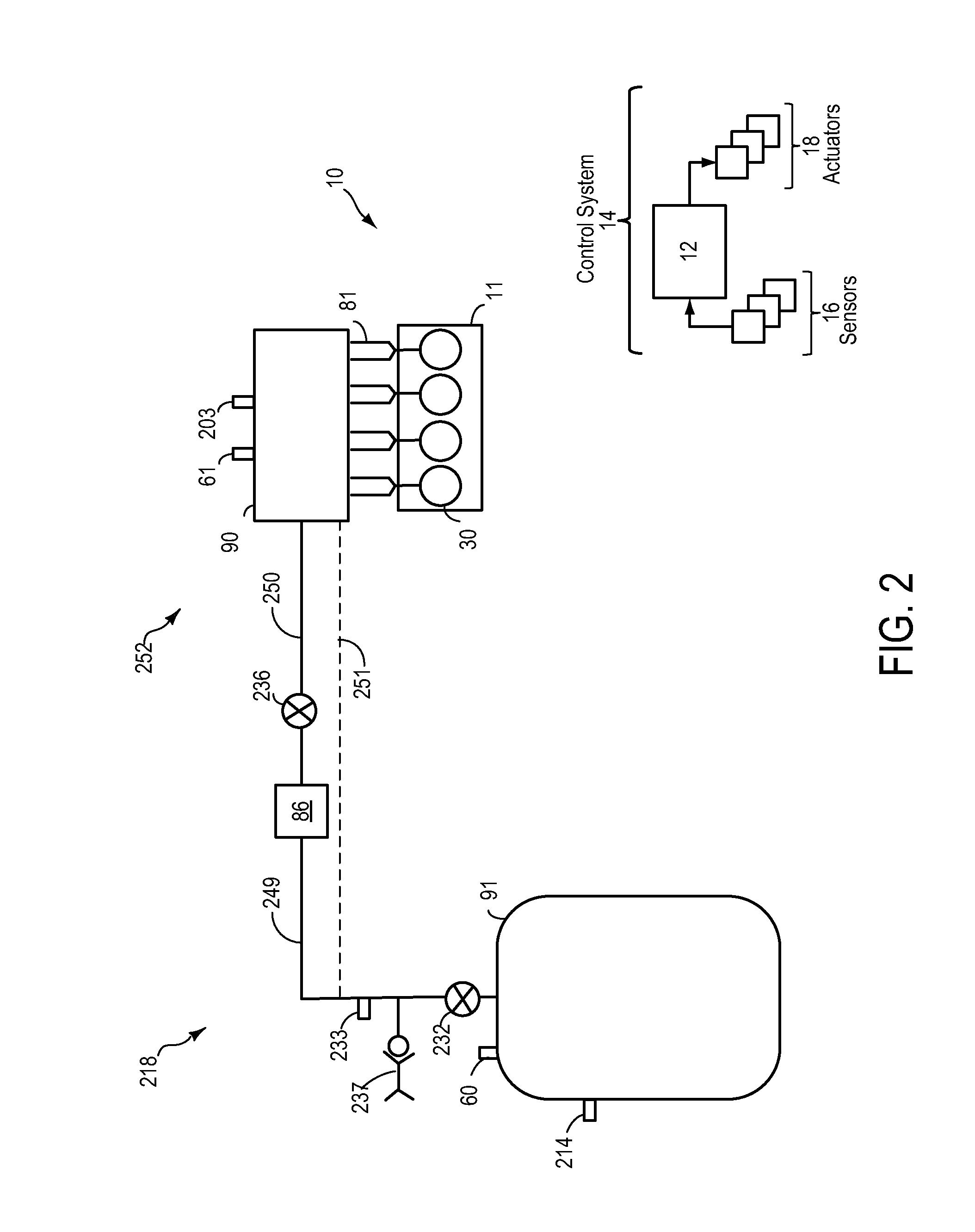
[0016]The present description is related to a method for adjusting the amount of gaseous fuel injected based on a calculated sonic choke flow rate, and co-fueling the engine with a liquid fuel in order to meet a desired load on the engine. Because the methods relate to an engine system, FIGS. 1-3 show schematic diagrams of exemplary systems within the engine. Then, FIG. 4 shows an example flow rate through a restriction during a choked sonic flow where the flow velocity remains constant. In FIGS. 5 and 6, flow charts of example methods for adjusting the rate of flow to substantially minimize time for fuel tank emptying while maintaining on average mass flow rate from the fuel injector to be less than mass flow rate of gaseous fuel delivered through a restriction to the fuel injector are included to illustrate the method. FIG. 7 then shows a simulated operating sequence according to the methods of FIGS. 5 and 6 when the engine has port gaseous fuel injectors. Thus, the sequence of FI...


PUM


Abstract

A method is described for adjusting the amount of gaseous fuel injected based on the sonic choked flow rate through a restriction. Because the sonic choke flow rate continues to decrease as tank pressure decreases, the method includes computing the sonic choke flow rate through the restriction based on system variables and enforcing the rate of CNG injection to be less than the sonic choke flow rate through the restriction. Thereby, the mass flow rate to the fuel injector can be substantially maximized to substantially minimize the time for fuel tank emptying, particularly during the last amount of tank emptying when the contents of the gaseous storage tank is low.

Description

FIELD[0001]The field of the description relates to vehicle fuel systems operating with gaseous fuels.BACKGROUND AND SUMMARY[0002]Motor vehicles are known that operate on compressed natural gas. CNG is routed through a restriction and pressure regulator to supply CNG at a constant pressure to the engine fuel injectors.[0003]A problem with motor vehicles operating on CNG is that as the tank nears empty, CNG supply to the engine fuel injector is no longer at constant pressure. Consequently, accurate control of the amount of CNG delivered to the engine becomes difficult to control as the fuel tank empties resulting in poor drivability and difficult emission controls.[0004]One approach to addressing this problem has been to require tank refill when CNG pressure (e.g. tank pressure or fuel injection pressure) falls below a predetermined value. This type of approach results in frequent tank refills and limitation of the vehicle range of operation.[0005]In another approach, for vehicles tha...

Claims


Application Information

Patent Timeline
Patent Type & Authority Applications(United States)
IPC IPC(8): F02M21/02F02M43/00F02M37/00
CPCF02M21/0239F02M43/00F02M37/0017F02M43/04F02M69/54F02M21/0215Y02T10/30F02D19/027F02D19/061F02D19/0628F02D19/0647
Inventor PURSIFULL, ROSS DYKSTRAGUIDO, SAMUELBADILLO, EDSABERWAL, DEV
Owner FORD GLOBAL TECH LLC
Why Eureka
Try Eureka