Method and apparatus for graphic processing using parallel pipeline

a parallel pipeline and graphic processing technology, applied in the field of graphic processing, can solve the problems of trv and ray primitive ist operations being computationally expensive, further consuming relatively large amounts of power, and ray tracing having a disadvantage in achieving high-speed rendering

Inactive Publication Date: 2014-02-20
KONGJU NAT UNIV IND UNIV COOPERATION FOUND +1
View PDF4 Cites 29 Cited by
  • Summary
  • Abstract
  • Description
  • Claims
  • Application Information

AI Technical Summary

Problems solved by technology

However, ray tracing has a disadvantage in terms of a difficulty in achieving high-speed rendering due to a great amount of elementary operati

Method used


Image

  • Method and apparatus for graphic processing using parallel pipeline
  • Method and apparatus for graphic processing using parallel pipeline
  • Method and apparatus for graphic processing using parallel pipeline

Examples


Embodiment Construction

[0049]Reference will now be made in detail to embodiments, examples of which are illustrated in the accompanying drawings, wherein like reference numerals refer to like elements throughout. Embodiments are described below to explain the present disclosure by referring to the figures.

[0050]The term “ray” as used herein may include a ray object for ray tracing, a data structure representing a ray, information of a ray, and data associated with a ray, and these may be used interchangeably.

[0051]The term “shading unit” used in the description may also be referred to as a “shader”.

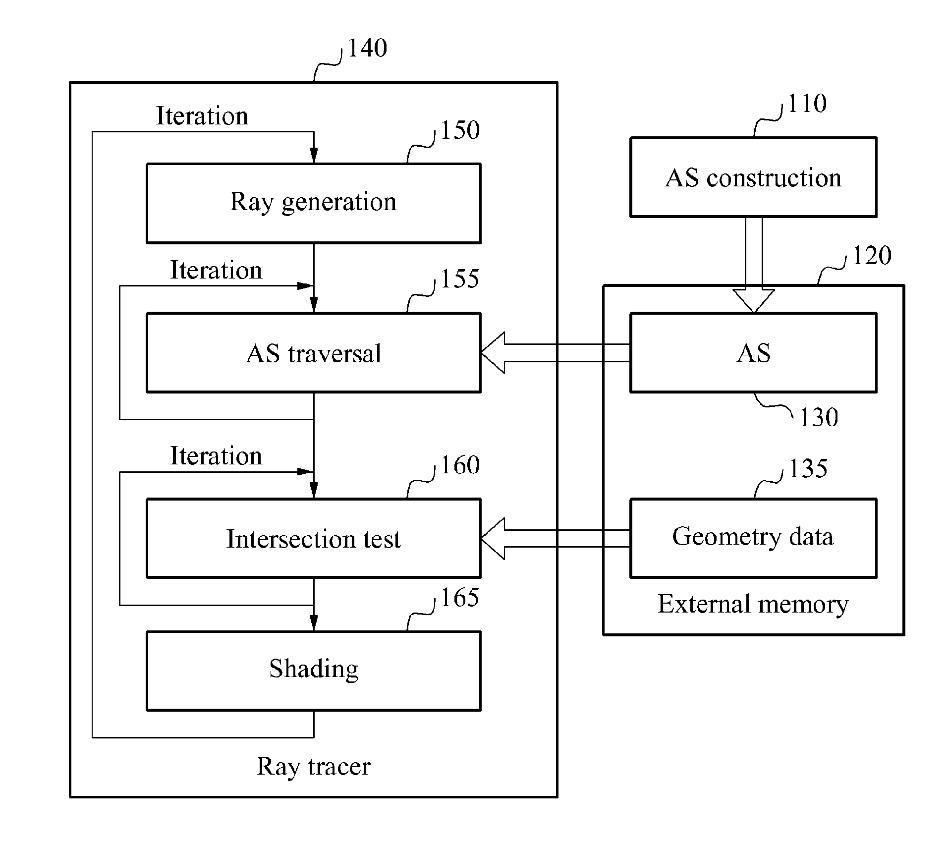
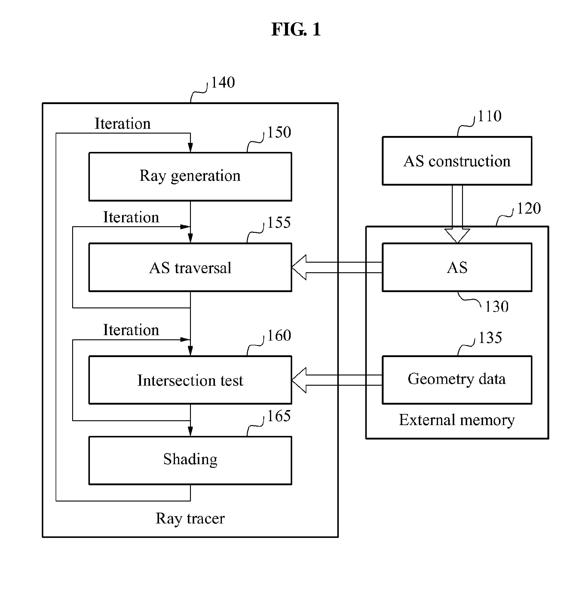
[0052]FIG. 1 illustrates an example of ray tracing.

[0053]Referring to FIG. 1, an acceleration structure (AS) construction 110 represents an operation or process of constructing an AS 130 in an electronic device. The electronic device may be embodied as a computer, a personal computer, a portable computer, a mobile device such as a mobile phone, a smart phone, a personal media player, tablet, and the like. Gener...


PUM


Abstract

An apparatus and method for ray tracing includes a traversal (TRV) unit using a tree acceleration structure (AS). The TRV unit may include a plurality of sub-pipeline units configured to perform different operations required for ray TRV using the tree AS and to operate in parallel.

Description

CROSS-REFERENCE TO RELATED APPLICATIONS[0001]This application claims the priority benefit of Korean Patent Application No. 10-2012-0089682, filed on Aug. 16, 2012, in the Korean Intellectual Property Office, the disclosure of which is incorporated herein by reference.BACKGROUND[0002]1. Field[0003]Example embodiments disclosed herein relate to a method and apparatus for graphic processing, and more particularly, to a method and apparatus for ray tracing.[0004]2. Description of the Related Art[0005]Three-dimensional (3D) rendering refers to a process for processing data of a 3D object into an image viewed from a given viewpoint of a camera.[0006]Among rendering techniques, rasterization generates an image by displaying a 3D object into a scene. Ray tracing generates an image by tracing a path of incident light of which a ray is emitted from a viewpoint of a camera to each pixel of the image.[0007]Ray tracing has an advantage of generating a high-quality image using physical properties...

Claims


Application Information

Patent Timeline
IPC IPC(8): G06T1/20G06T15/06
CPCG06T15/06G06T1/20G06T15/005G06T2210/52
Inventor LEE, WON JONGSHIN, YOUNG SAMLEE, JAE DONKIM, JIN WOOPARK, HUN SANG
Owner KONGJU NAT UNIV IND UNIV COOPERATION FOUND
Why Eureka
Try Eureka