Non-Linear VDR Residual Quantizer

a residual quantizer and non-linear technology, applied in the field of images, can solve problems such as severe picture artifacts, and the inability to transmit actual captured vdr content best, and achieve the effect of reducing the cost of production and maintenan

Inactive Publication Date: 2014-02-20
DOLBY LAB LICENSING CORP
View PDF6 Cites 81 Cited by
  • Summary
  • Abstract
  • Description
  • Claims
  • Application Information

AI Technical Summary

Problems solved by technology

To conserve bandwidth or for other considerations, transmission of the actual captured VDR content may not be a best approach.
Without any preprocessing, direct coding of a VDR residual using a traditional SDR compressor, such as those described by the MPEG coding standards, may cause severe picture artifacts, such as blockiness and banding.

Method used


Image

  • Non-Linear VDR Residual Quantizer
  • Non-Linear VDR Residual Quantizer
  • Non-Linear VDR Residual Quantizer

Examples


Embodiment Construction

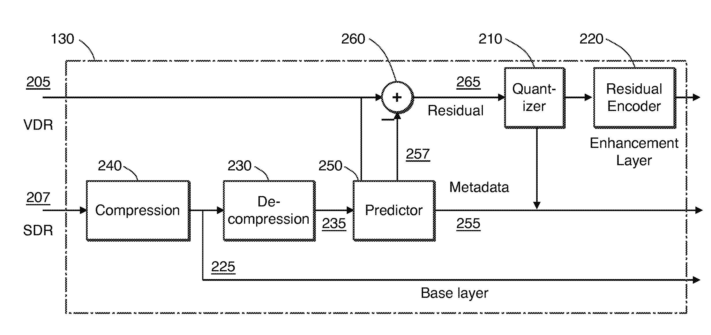
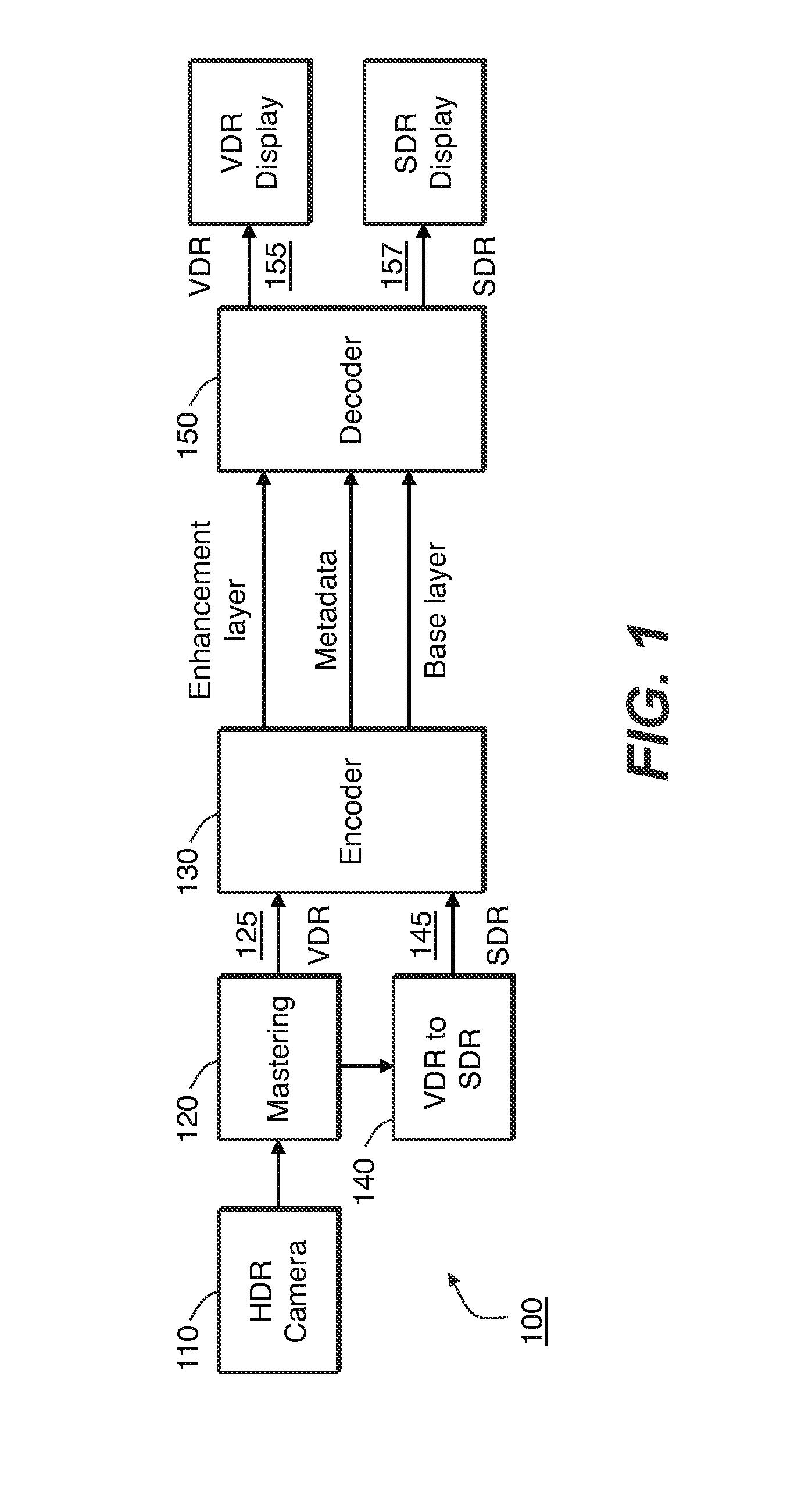
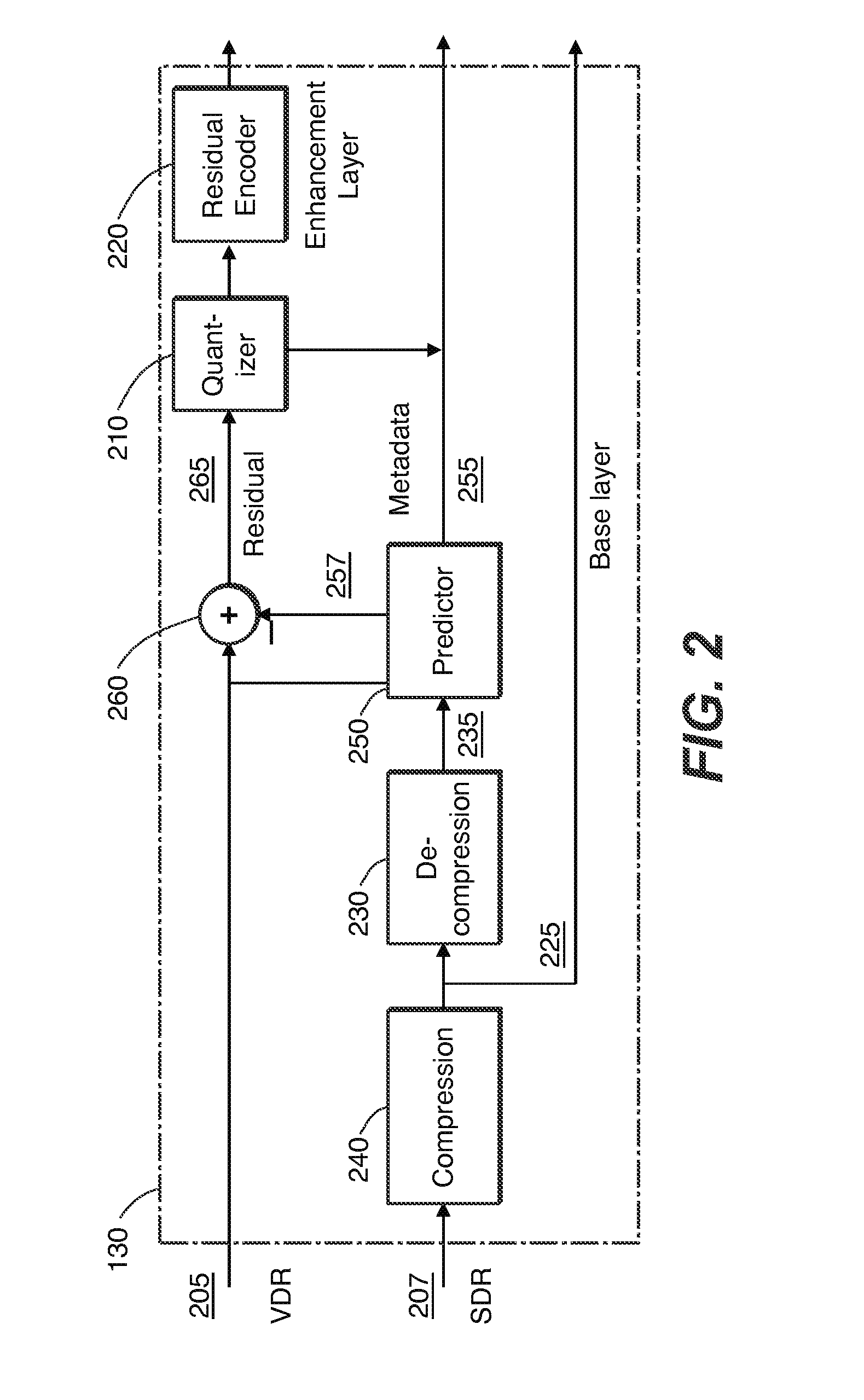
[0024]Given a pair of corresponding VDR and SDR images, such as images that represent the same scene, each at different levels of dynamic range, improved coding of the residual signal in layered VDR coding is achieved. The VDR image is coded by combining a base layer (e.g., the SDR image) and a residual as an enhancement layer. In an embodiment, the enhancement layer comprises a difference between the original VDR image and a version thereof that is predicted, e.g., from the base layer. In the following description, for the purposes of explanation, numerous specific details are set forth in order to provide a thorough understanding of the present invention. It will be apparent, however, that the present invention may be practiced without these specific details. In other instances, well-known structures and devices are not described in exhaustive detail, in order to avoid unnecessarily occluding, obscuring, or obfuscating the present invention.

[0025]Overview

[0026]Example embodiments ...


PUM


Abstract

In layered VDR coding, inter-layer residuals are quantized by a non-linear quantizer before being coded by a subsequent encoder. Several non-linear quantizers are presented. Such non-linear quantizers may be based on sigmoid-like transfer functions, controlled by one or more free parameters that control their mid-range slope. These functions may also depend on an offset, an output range parameter, and the maximum absolute value of the input data. The quantizer parameters can time-vary and are signaled to a layered decoder. Example non-linear quantizers described herein may be based on the mu-law function, a sigmoid function, and / or a Laplacian distribution.

Description

CROSS-REFERENCE TO RELATED APPLICATIONS[0001]This application claims priority to U.S. Provisional Patent Application No. 61 / 478,836 filed 25 Apr. 2011, which is incorporated herein by reference in its entirety.TECHNICAL FIELD OF THE INVENTION[0002]The present invention relates generally to images. More particularly, an embodiment of the present invention relates to the non-linear quantization and de-quantization of the residual signal in layered coding of high dynamic range images.BACKGROUND OF THE INVENTION[0003]As used herein, the term ‘dynamic range’ (DR) may relate to a capability of the human psychovisual system (HVS) to perceive a range of intensity (e.g., luminance, luma) in an image, e.g., from darkest darks to brightest brights. In this sense, DR relates to a ‘scene-referred’ intensity. DR may also relate to the ability of a display device to adequately or approximately render an intensity range of a particular breadth. In this sense, DR relates to a ‘display-referred’ inte...

Claims


Application Information

Patent Timeline
Patent Type & Authority Applications(United States)
IPC IPC(8): H04N7/26
CPCH04N19/00909H04N19/00096H04N19/46H04N19/136H04N19/186H04N19/192H04N19/36G06F3/1423G09G5/10G09G2320/0271H04N19/126H04N21/2365H04N19/86H04N19/40H04N19/00
Inventor SU, GUAN-MINGYUAN, YUFEIQU, SHENG
Owner DOLBY LAB LICENSING CORP
Why Eureka
Try Eureka