Bone transport external fixation frame

a fixation frame and bone technology, applied in the field of bone transport external fixation frame, can solve the problems of limited patient access, difficult for patients to make the required daily adjustments, and generally not allowing significant manipulation of the external fixation fram

Active Publication Date: 2014-02-27
STRYKER EURO OPERATIONS HLDG LLC
View PDF9 Cites 26 Cited by
  • Summary
  • Abstract
  • Description
  • Claims
  • Application Information

AI Technical Summary

Benefits of technology

[0013]In accordance with still yet another embodiment of this first aspect, the plurality of elongate struts further includes a threaded shaft and a position adjustment member coupled to each of the plurality of ring transport assemblies, each position adjustment member adapted to transport along a length of the threaded shaft in the proximal and distal directions. Each position adjustment member has a semi-locked position such that the location of each position adjustment member on the threaded shaft is constant when the threaded shaft is not being rotated in either clockwise or counterclockwise directions about the central axis of the plurality of elongate struts and has an unlocked position such that the location of each position adjustment member can transport in either the proximal or distal directions without the threaded shaft being rotated in either the clockwise or counterclockwise directions about the central axis of the plurality of elongate struts.

Problems solved by technology

A problem that may arise out of this is that such external fixation frames generally do not allow significant manipulation of what may be referred to as a transport ring without disassembling and then reassembling the frame or adding new devices.
These position adjustments must be done where the nuts are secured, making it very difficult for the patient to make the required daily adjustments with consideration of stable fixation in mind.
Other devices use different techniques to adjust the effective length of the rods, but all must be adjusted somewhere between the ends, offering limited access for the patient.

Method used


Image

  • Bone transport external fixation frame
  • Bone transport external fixation frame
  • Bone transport external fixation frame

Examples


first embodiment

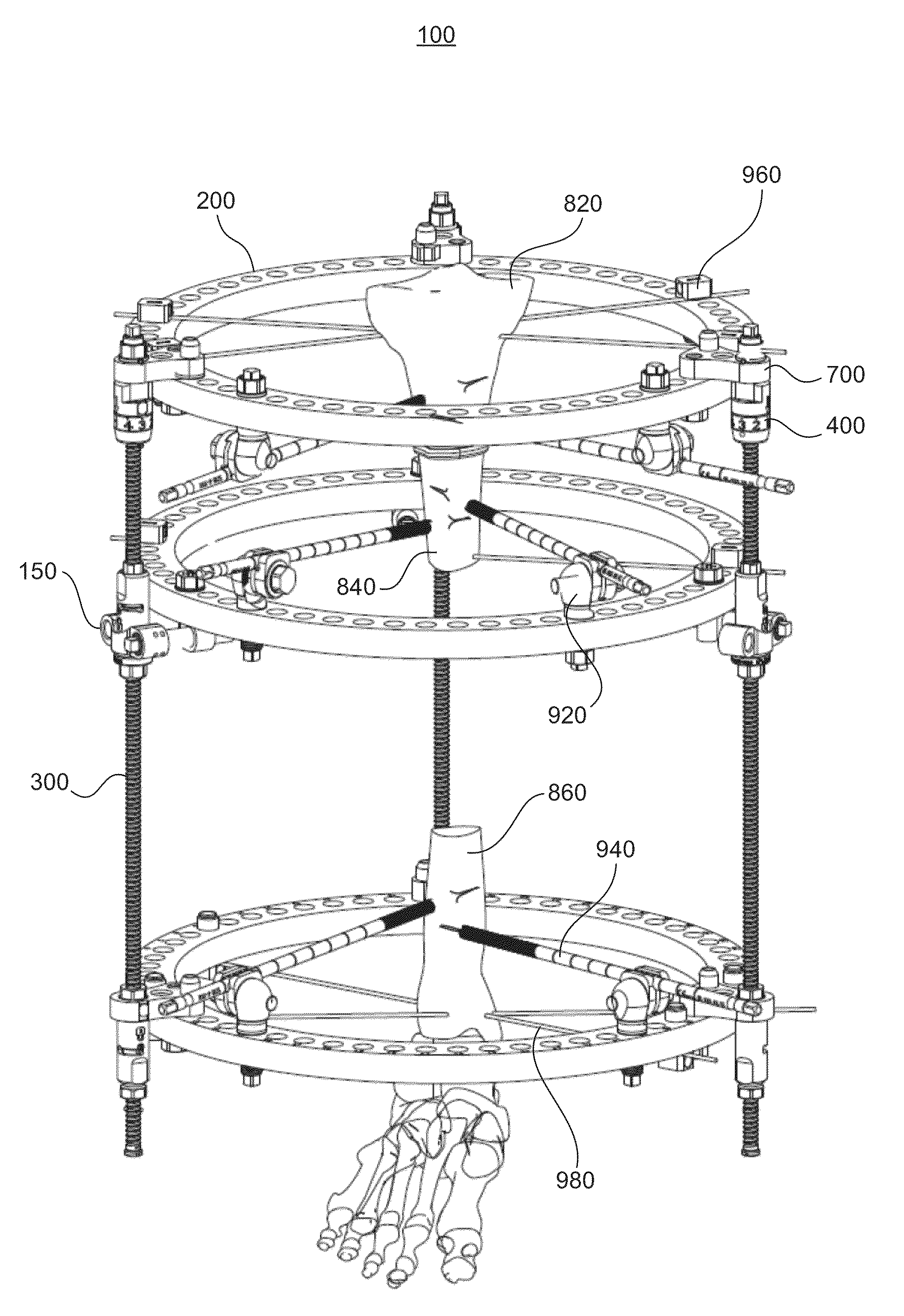
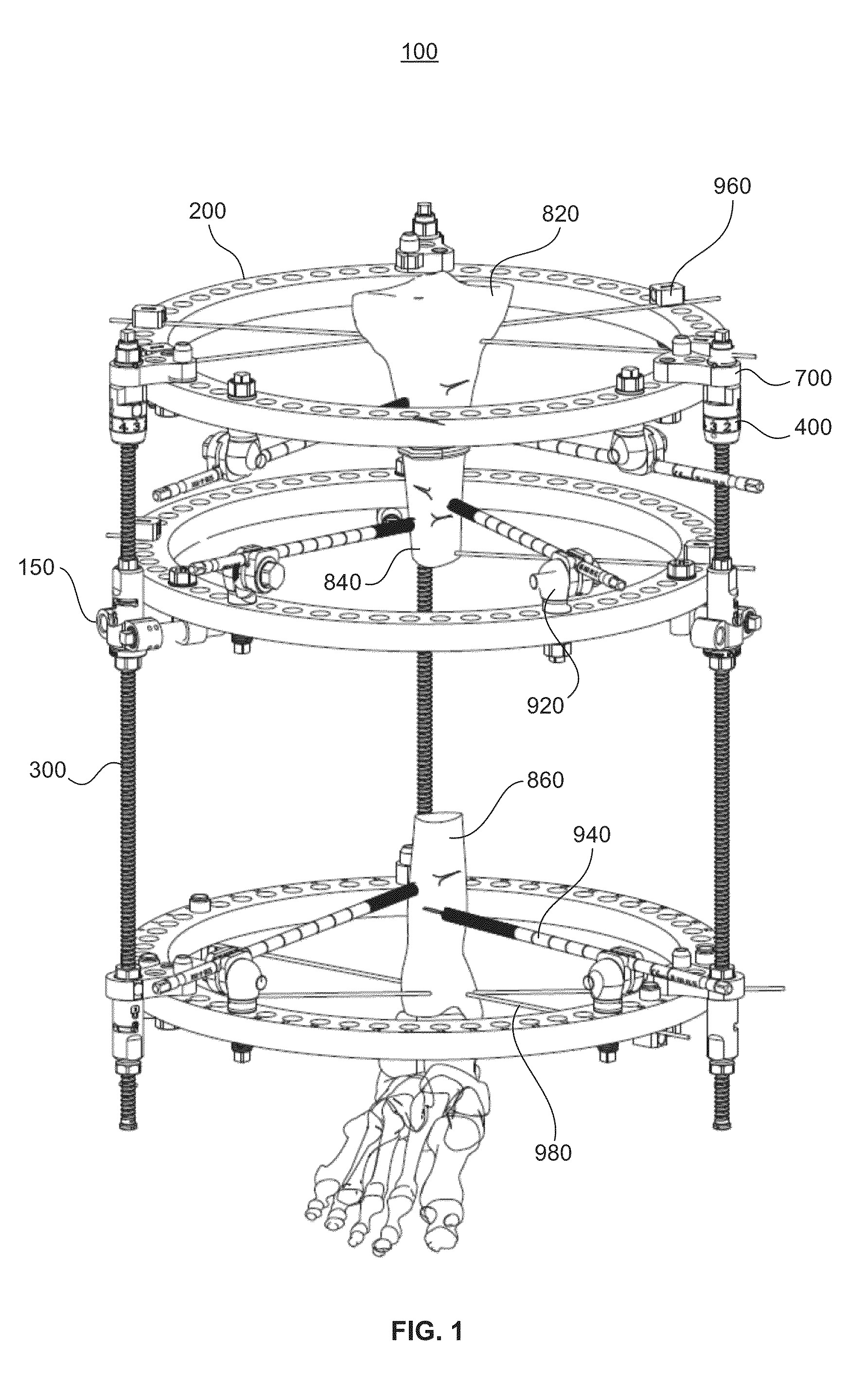
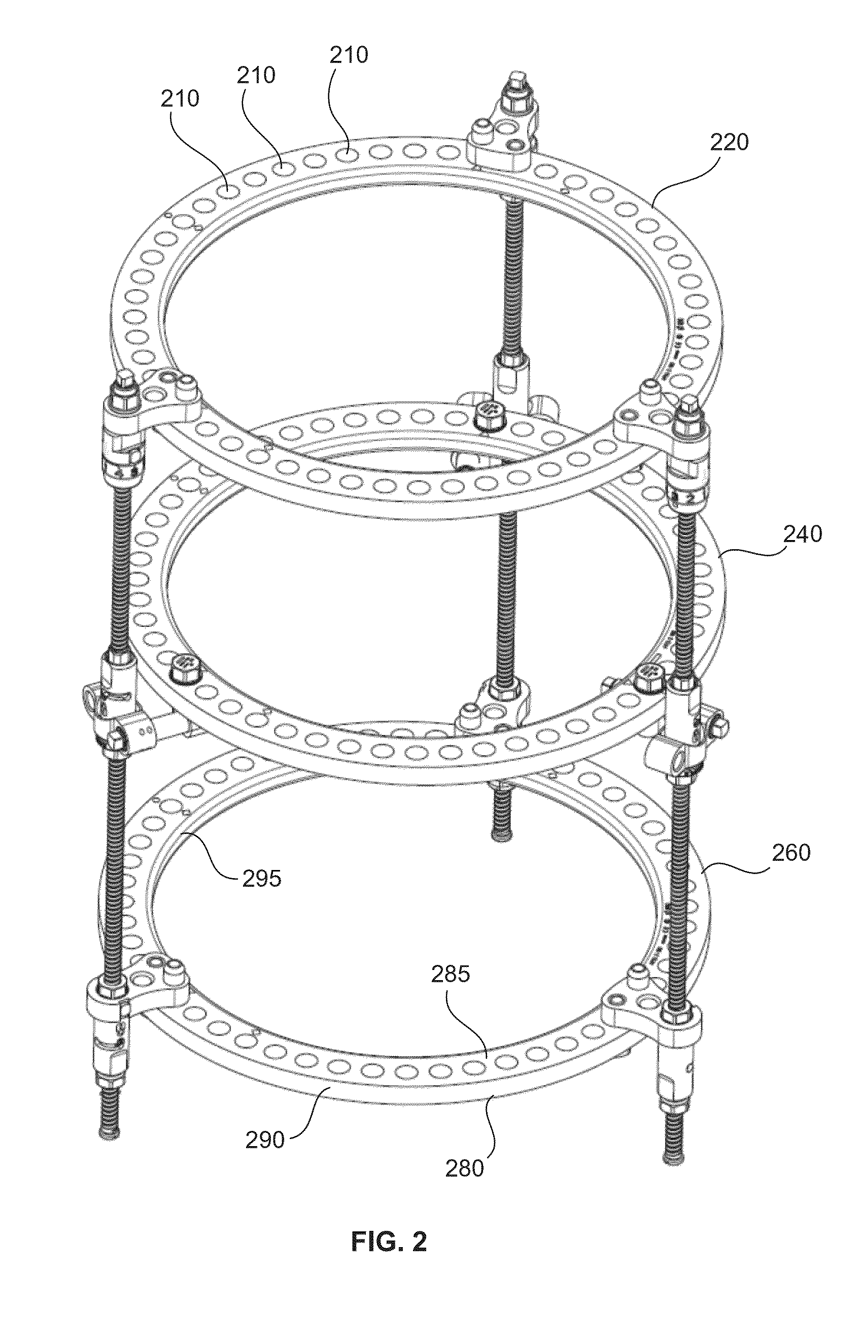
[0052]Referring to FIGS. 1-3, a bone transport frame 100 is shown. The bone transport frame 100 generally comprises a plurality of bone transport assemblies 150, a plurality of bone transport rings 200, a plurality of strut assemblies 300, a plurality of top click mechanisms 400, and a plurality of devices that interact with different segments or portions of a bone.

[0053]Each of the bone transport rings 200 has a lower ring surface 280 and an upper ring surface 285 as well as an outer ring surface 290 and an inner ring surface 295. Upper 285, lower 280, inner 295, and outer 290 ring surfaces are substantially flat such that each ring has a vertical cross section that is substantially rectangular. In other embodiments, ring surfaces 280, 285, 290 and 295 need not be flat, but rather can take on various shapes to accommodate other devices such as clamps, for example.

[0054]Along the circumference of each of the bone transport rings 200 resides a plurality of through-holes 210 that exte...

second embodiment

[0080]Referring to FIGS. 22-23, a bone transport frame 100′ is shown. The bone transport frame 100′ generally includes a plurality of bone transport assemblies 150′, a plurality of bone transport rings 200 and a plurality of strut assemblies 300.

[0081]One difference between the second embodiment shown in FIGS. 22-23 and the first embodiment shown in FIGS. 1-3 is that the bone transport assembly 150′ coupled to the medial ring 240 includes a different structure such that the gradual translation of the medial ring 240 does not occur by way of a clicking mechanism.

[0082]The second embodiment of the bone transport assembly 150′ comprises a quick release mechanism 600, a ball jointed flange 705, a series of hinge pin and bracket assemblies, a series of nuts, and a translational bolt.

[0083]The ball jointed flange 705 has a hyperbolic collar 595 much like the hyperbolic collar 595 seen on the ball joint 500 of the first embodiment. This ball jointed flange 705 is also coupled to the quick ...

third embodiment

[0084]Referring to FIGS. 24-28, there is shown a bone transport frame 100″. A difference between the bone transport frame 100″ shown in FIGS. 24-28 and previous embodiments is that medial ring 240 does not have the capability of horizontal translation.

[0085]Structurally speaking, the embodiment shown in FIGS. 24-28 is obtained by taking the embodiment of the bone transport frame 100′ shown in FIGS. 22-23, removing the translating bolt 730 and accessories, and directly attaching the ball jointed flange 705 to the medial ring 240. As disclosed elsewhere herein, the ball jointed flange 705 can connect to the medial ring 240 by virtue of a retaining pin 720 that extends through both a through-hole 210 of the medial ring 240 and through an anterior through-hole 740 of the ball jointed flange 705. This permits the medial ring 240 to move such that it is no longer parallel with proximal ring 220 and distal ring 260, but there are no mechanisms for translating medial ring 240 toward or away...


PUM


Abstract

Disclosed herein are systems and methods for manipulating the orientation of a plurality of bone fragments with respect to one another. A bone transport frame including first and second rings, a plurality of elongate struts, and a plurality of ring transport assemblies for orienting a first bone segment with respect to a second bone segment is disclosed. A third ring may be included in the bone transport frame for orienting a third bone segment with respect to the first and second bone segments. Manipulation of an adjustable member of the bone transport frame can transport a ring in either a proximal or distal direction with respect to other rings of the frame. Manipulation of another adjustable member of the bone transport frame can translate a central axis of one of the rings either toward or away from the central axes of the plurality of elongate struts.

Description

FIELD OF THE INVENTION[0001]The present invention relates to systems and methods for manipulating the orientation of a plurality of bone fragments with respect to one another, and in particular it relates to external fixation devices in which rings thereof may be manipulated with respect to one another via bone transport assemblies.BACKGROUND OF THE INVENTION[0002]External fixation frames may be used to correct skeletal deformities using the distraction osteogenesis process. The Ilizarov external fixation devices, for example, are widely used for this purpose. The Ilizarov-type devices may be used to translate bone segments by manipulating rings connected to each bone segment.[0003]External fixation devices generally utilize a plurality of threaded rods fixated to through-holes in the rings to build the frame. In order to build a desired frame, these rods generally have to have different lengths. A problem that may arise out of this is that such external fixation frames generally do...

Claims


Application Information

Patent Timeline
Patent Type & Authority Applications(United States)
IPC IPC(8): A61B17/62
CPCA61B17/62A61B17/66
Inventor SINGH, MANOJ KUMARCROZET, YVES STEPHANE
Owner STRYKER EURO OPERATIONS HLDG LLC
Why Eureka
Try Eureka