
Novel bone transport intramedullary nail

An intramedullary nail and a new type of technology, applied in the field of medical devices, can solve the problems of poor alignment of the transferred bone segment, long time for the patient to carry the frame, and easy infection of the nail tract, so as to shorten the fixation time, wide application range and convenient operation. Effect

Pending Publication Date: 2021-01-26
河南科科生物科技有限公司
View PDF0 Cites 0 Cited by
  • Summary
  • Abstract
  • Description
  • Claims
  • Application Information

AI Technical Summary

Problems solved by technology

[0003] The purpose of the present invention is to provide a new type of intramedullary nail for bone transfer to solve the problem of bone transfer of the external fixator proposed in the above background technology. Clinical problems such as poor alignment and multiple adjustments

Method used


Image

  • Novel bone transport intramedullary nail
  • Novel bone transport intramedullary nail
  • Novel bone transport intramedullary nail

Examples


Embodiment 1

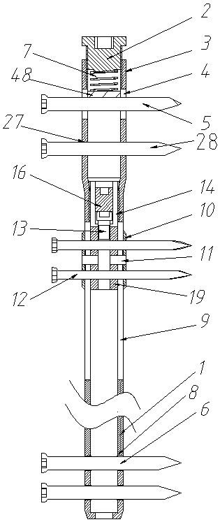
[0039] Example 1, such as figure 1 As shown, a new type of intramedullary nail for bone transfer includes a main nail of the intramedullary nail. The main nail of the intramedullary nail is a hollow structure. , the proximal end 3 of the intramedullary nail and the main body 1 of the intramedullary nail are integrally structured, the diameter of the proximal end 3 of the intramedullary nail is greater than the diameter of the main body 1 of the intramedullary nail, and the proximal end 3 of the intramedullary nail is provided with upper and lower The penetrating power screw hole 4 and the static screw hole 27 are provided with two penetrating fixing screw holes 8 on the intramedullary nail body 1 away from the proximal end 3 of the intramedullary nail. The power screw hole 4, the static screw hole A dynamic bone screw 5 , a static bone screw 28 , and a fixed bone screw 6 are respectively installed in the hole 27 and the fixing screw hole 8 , and the dynamic bone screw 5 can mo...

Embodiment 2

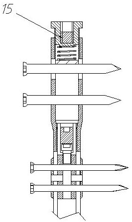
[0043] Example 2, such as figure 2 As shown, the difference between this embodiment and Embodiment 1 is that an upper magnetic body 15 is fixed inside the tail cap 2, and the upper magnetic body 15 can drive the tail cap 2 up and down along the proximal end 3 of the intramedullary nail under the action of an external magnetic field. Move, and then change the stress of the pressure-regulating spring-7, and adjust the bone end stress of moving the bone segment.

Embodiment 3

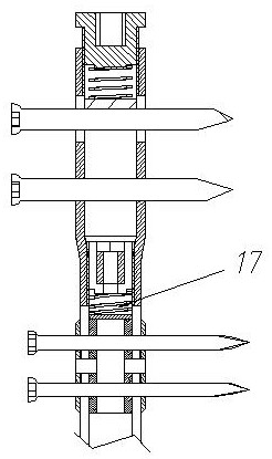
[0044] Example 3, such as image 3 As shown, the difference between this embodiment and Embodiment 1 is that the connector is a spring two 17, the upper end of the spring two 17 is in contact with the lower end surface of the adjusting screw sleeve 14, and the lower end is provided with a spring base, and the spring base is formed by the inner guide sleeve 19 support.


PUM


Abstract

The invention discloses a novel bone transport intramedullary nail. The novel bone transport intramedullary nail comprises a main intramedullary nail; the main intramedullary nail is of a hollow structure and comprises an intramedullary nail near end and an intramedullary nail main body; the intramedullary nail near end and the intramedullary nail main body are of an integrated structure; the diameter of the intramedullary nail near end is larger than that of the intramedullary nail main body; a power screw hole and a static screw hole which are through are formed in the intramedullary nail near end; an adjusting hole is formed in the portion, away from the intramedullary nail near end, of the intramedullary nail main body; a power bone screw is installed in the power screw hole and can move in the axial direction of the power screw hole; a tail cap is installed at the intramedullary nail near end; an elastomer I is arranged between the tail cap and the power bone screw; and a bone transport device for adjusting movement of a fracture end is arranged on the intramedullary nail main body. An elastic device can give stress stimulation to the bone segment, avoid stress shielding, accelerate fracture healing, reduce delayed healing and non-healing of fracture and reduce the occurrence rate of fracture after the intramedullary nail is removed.

Description

technical field [0001] The invention belongs to the field of medical equipment, and in particular relates to a novel intramedullary nail for bone transfer. Background technique [0002] In orthopedic clinics, patients with long-segment bone defects caused by trauma, inflammation, tumors, etc. are generally treated with external fixation brackets. Osteotomy is performed at the proximal or distal end of the bone defect, and bone is moved to repair the bone defect. The structure of the external fixation bracket is complex, and the patient has been wearing the frame for a long time, the screw channel is prone to infection, the bone screw or Steiner wire used for fixation is easy to affect the sliding of the muscle and tendon, and it is easy to cause joint stiffness. Adjustment and other disadvantages. Therefore, designing a bone-transporting intramedullary nail that can perform bone transport and is suitable for different bone segment defects is a clinical problem that needs to...

Claims


Application Information

Patent Timeline
IPC IPC(8): A61B17/72
CPCA61B17/72
Inventor 宋文超王秋霞宋若怡王爱国肖鹏甄相周李旭丁焕文陈山林刘波万圣祥王剑利姚忠军沈先涛戚剑熊洪涛刘赵华马长生田耘卢冰宋德业张银光王建卫杨斌奎王栋梁敖荣广王大伟郭军陈龙丁坚李峰陈顺有柳申鹏杨素敏唐举玉吴攀峰高顺红魏鹏叶朝辉叶川刘承伟王恒池雷霆魏杰高海军李正勋黄根东
Owner 河南科科生物科技有限公司
Learn More