Passive, reversible deformation sensor

Active Publication Date: 2014-03-06
ETAT FR REPRESENTE PAR LE DELEGUE GENERAL POUR LARMEMENT +1
View PDF6 Cites 2 Cited by
  • Summary
  • Abstract
  • Description
  • Claims
  • Application Information

AI Technical Summary

Benefits of technology

The invention provides a reversible and passive deformation sensor for cycles of deformations in a structure. The sensor comprises a support with two portions that attach to the structure, and detecting means associated with each of the support portions. The detecting means have the capability to distinguish between different thresholds of changes in distance between two points or areas. The sensor can be positioned on a structure using an elastic element and can be used to detect and count cycles of deformations. Additionally, a reverse running stop device can be associated with the sensor to prevent the teethed wheel from running backwards. The sensor has a low surface footprint and can be used to measure changes in the distance between two points or areas with high accuracy.

Problems solved by technology

The second one relates to the impossibility to use them with a complete pyrotechnic security.
Indeed, the presence of a potential difference, and thus of an electrical current, creates a risk of spark formation or short circuit which could generate a fire or even an explosion in presence of explosive material.
In addition, in most cases, these sensors and associated processing means have a large size, typically of several tens centimeters, thus making them very visible and which explains why they are subject to acts of vandalism.
However, where the structure subjected to these deformations is of a small size or has a reduced potential implantation area, and where several detection thresholds must be performed, its surface may not be sufficiently large to arrange as many different microsensors as different thresholds to be detected.

Method used


Image

  • Passive, reversible deformation sensor
  • Passive, reversible deformation sensor
  • Passive, reversible deformation sensor

Examples


Embodiment Construction

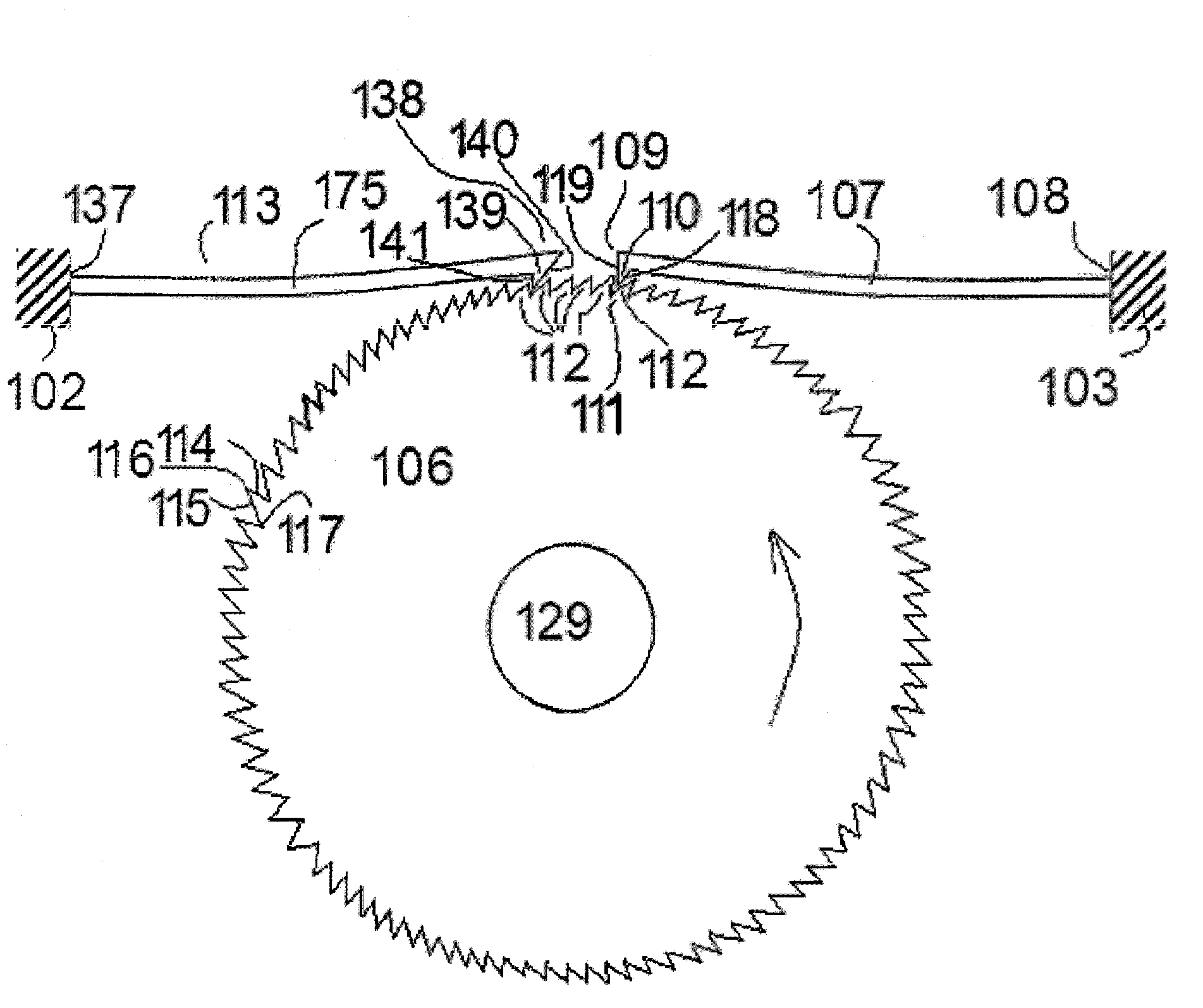
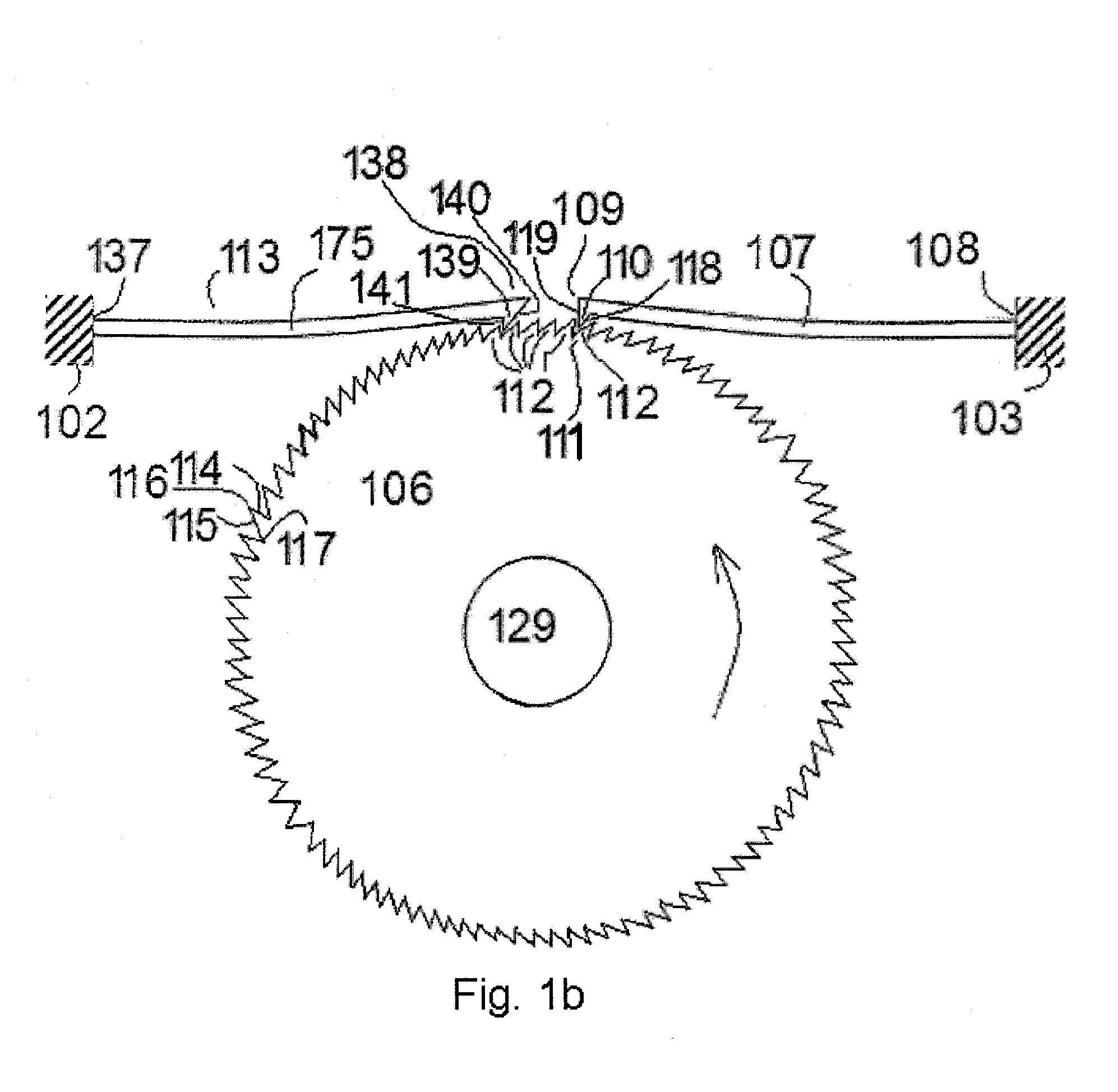
[0045]FIG. 2 shows a diagram of a first alternative embodiment of a support 9 usable in a reversible and passive sensor of deformations in a direction OX of a structure according to the invention.

[0046]This support 9 is provided with two L-shaped sub-assemblies 10, 11, arranged head-to-foot and separated by a gap 12 and respective bases 13, 14 of which are, in part, anchor areas for anchoring the support 9 on the structure to be monitored.

[0047]In this exemplary embodiment, these bases 13, 14 each comprise two bores 15, 16 and 17, 18. The axes Y1 and Y2 passing respectively through the centers of the bores 15, 16 and 17, 18 are perpendicular to the axis OX while the axes X1 and X2 passing respectively through the centers of the bores 15, 17 and 16, 18 are parallel to the axis OX.

[0048]The second portions 21, 23 of the Ls perpendicular to the respective bases 13 and 14 are positioned along the axis OX.

[0049]The second portion 21 of the first sub-assembly 10 is provided with three bor...


PUM


Abstract

The present invention relates to the field of microsensors, and particularly to a passive and reversible deformation sensor, specifically cycles of deformations in a direction OX of a structure, specifically during cycles of temperatures or mechanical stresses to which the structure is subjected, this sensor including elements (4, 5, 6) for detecting and, preferably, counting cycles of variations in the distance between two points or areas of a structure, these elements including a support having first and second portions (41, 44) attachable to, respectively, either of the two points or areas of the structure, wherein the detecting elements are associated with each of the first and second portions of the support, sensor characterized by in that the detecting elements include elements (541, 542, 543, 551, 552, 553, 561, 562, 563) for distinguishing between at least two different thresholds of cycles of variations in distance.

Description

CROSS-REFERENCE TO RELATED APPLICATIONS[0001]This application is a U.S. National Phase application under 35 U.S.C. §371 of International Application No. PCT / FR2012 / 000155, filed Apr. 20, 2012, which claims priority of French patent application no. 1101274 filed on Apr. 22, 2011.FIELD OF THE INVENTION[0002]The present invention relates to the field of microsensors, and particularly to a microsensor able to detect, and preferably also to count, cycles of variations in the distance between two points or areas of a structure subjected to a repeated external action, for example cycles of temperatures or mechanical stresses as for example the number of passes of vehicles across a bridge, generating a known stress level in the structure.DESCRIPTION OF THE RELATED ART[0003]In this respect, patent U.S. Pat. No. 5,452,335 is known, which describes several examples of sensor of cycles of temperature, of which, on one hand, a first example, shown in FIGS. 1 and 2 and in column 4, of a passive s...

Claims


Application Information

Patent Timeline
IPC IPC(8): G01D9/00
CPCG01D9/00G01B5/30G01K7/01G01Q80/00
Inventor LOUVIGNE, PIERRE-FRANCOISMINOTTI, PATRICEVESCOVO, PAULWALTER, VINCENT
Owner ETAT FR REPRESENTE PAR LE DELEGUE GENERAL POUR LARMEMENT
Why Eureka
Try Eureka