Unfoldable layered connection, and method for manufacturing an unfoldable layered connection

Pending Publication Date: 2021-11-25
INL INT IBERIAN NANOTECH LAB
View PDF0 Cites 0 Cited by
  • Summary
  • Abstract
  • Description
  • Claims
  • Application Information

AI Technical Summary

Benefits of technology

[0005]It is an object of the present inventive concept to mitigate, alleviate or eliminate one or

Problems solved by technology

Several applications require placement of a device in locations that are hard to r

Method used


Image

  • Unfoldable layered connection, and method for manufacturing an unfoldable layered connection
  • Unfoldable layered connection, and method for manufacturing an unfoldable layered connection
  • Unfoldable layered connection, and method for manufacturing an unfoldable layered connection

Examples


Example

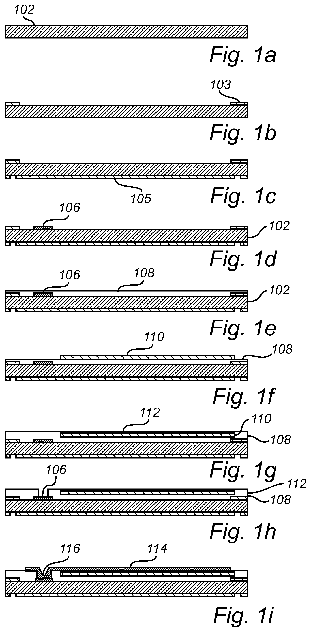
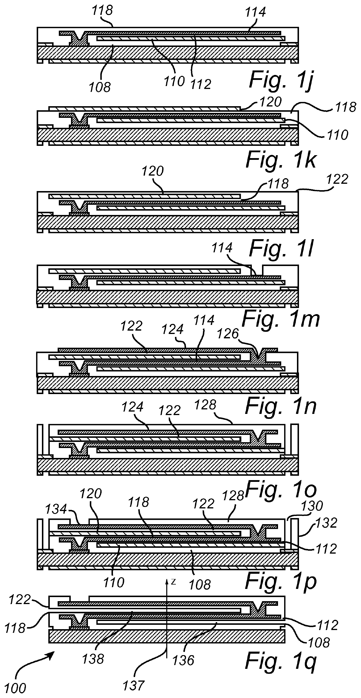
[0075]It may be repeated that some parts of the processes in the present disclosure may be omitted for the sake of brevity. In particular, some steps of masking, patterning, or etching may be omitted since it is believed that the person skilled in the art understands from the present disclosure as a whole how these steps are to be carried out within the present inventive concept. Some possible techniques which may be incorporated into the method described below include chemical vapor deposition (CVD), plasma etching, ashing, reactive ion etching (RIE), dry etching, inductively coupled plasma etching, lithography, and sputtering.

[0076]Further, it should be noted that the illustrated figures are not necessarily drawn to scale.

[0077]For the sake of clarity, it should also be noted that the disclosures made below in conjunction with FIGS. 1a-1q comprise optional steps of depositing, patterning, forming, or providing layers of different materials, such as e.g. connector material and flex...


PUM

PropertyMeasurementUnit
Thicknessaaaaaaaaaa
Electrical conductivityaaaaaaaaaa
Flexibilityaaaaaaaaaa

Abstract

The present inventive concept relates to an unfoldable layered connection comprising: a substrate; a node of connector material arranged to contact the substrate; a first extension comprising a core of connector material arranged to be in contact with the node, and flexible material arranged to at least partially enclose the core; a second extension comprising a core of connector material arranged to be in contact with the first extension via a second node of connector material, wherein the first extension is configured to be hingedly connected to the node, thereby allowing unfolding of the first extension along a z-axis being perpendicular to an extension plane of a major surface of the substrate; and wherein the second extension is hingedly connected to the second node, thereby allowing unfolding of the second extension along the z-axis, and wherein the second node is moveable along the z-axis via unfolding of the first extension.

Description

TECHNICAL FIELD[0001]The inventive concept described herein generally relates to the field of semiconductor device fabrication.BACKGROUND[0002]There has been a significant amount of research on connecting rigid integrated circuits to flexible interconnects. Several applications require placement of a device in locations that are hard to reach or benefit from flexible connections due to mechanical damage susceptibility. Examples include biomedical devices such as flexible neural interfaces, read-write magnetic heads, flexible displays, and lab-on-a-chip devices.[0003]Some adopted solutions consist of relatively long flexible connections from the device to the outside environment. This may be achieved by fabrication of metal connections on flexible substrates. A relatively large area is often occupied by the connection structure compared to the device itself. Other solutions concern die attachment to flexible substrates, e.g. Chip-on-flex (COF) technologies. These technologies package...

Claims


Application Information

Patent Timeline
IPC IPC(8): H01L23/00H01L23/14H05K3/32
CPCH01L24/29H01L24/27H01L23/147H01L2224/29083H01L2224/27001H01L2224/27614H05K3/32H05K1/028H05K3/4644H05K3/4691H05K2201/0154H05K2201/09109H05K2201/09672H05K2203/0769H05K2203/0789H05K2203/1152H05K2203/308H01L23/13H01L23/49822H01L23/4985H01L23/5383H01L23/5387
Inventor ALVES DIAS, ROSANA MARIAJOÂO, CARLOS AZEVEDO GASPAR
Owner INL INT IBERIAN NANOTECH LAB
Why Eureka
Try Eureka