Nail printing apparatus and printing control method

a printing apparatus and nail technology, applied in the field of nail printing apparatus, can solve the problems of increasing apparatus weight and cost, image distortion, and inability to adjust the position of the imaging device, and achieve the effect of low cost and without complicated and large structur

Inactive Publication Date: 2014-03-06
CASIO COMPUTER CO LTD
View PDF12 Cites 52 Cited by
  • Summary
  • Abstract
  • Description
  • Claims
  • Application Information

AI Technical Summary

Benefits of technology

[0016]The present invention advantageously provides a nail printing apparatus capable of acquiring nail images app...

Problems solved by technology

In such a conventional nail printing apparatus, however, the imaging device is fixed to the upper part of the apparatus, for example, and the position of the imaging device cannot be adjusted.
As a result, the apparatus increases in weight and cost.
Therefore, photographing with a wide-angle lens produces an image with a large distortion and makes it dif...

Method used


Image

  • Nail printing apparatus and printing control method
  • Nail printing apparatus and printing control method
  • Nail printing apparatus and printing control method

Examples


first embodiment

[0036]A nail printing apparatus in a first embodiment of the present invention is described with reference to FIGS. 1 to 8.

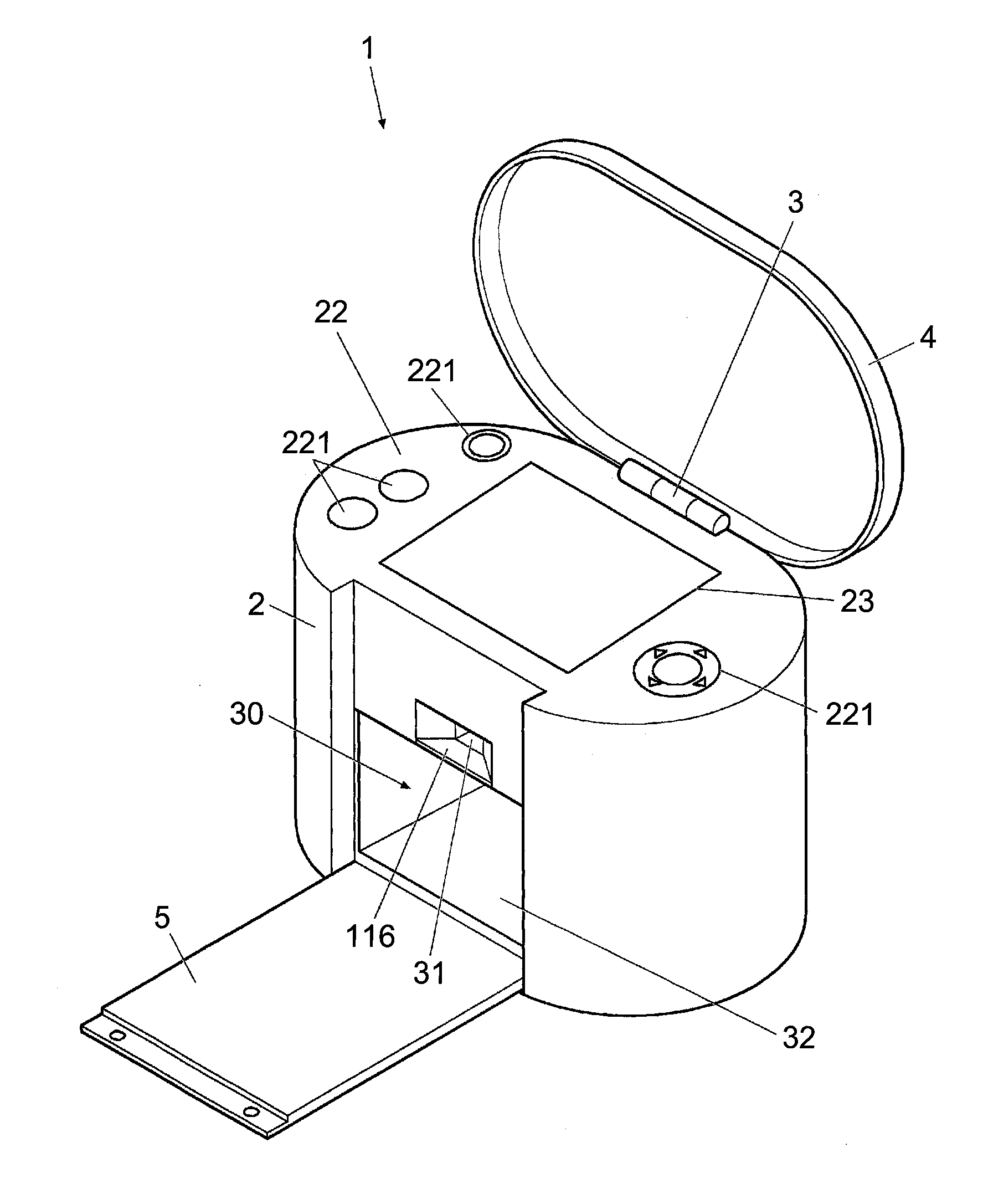
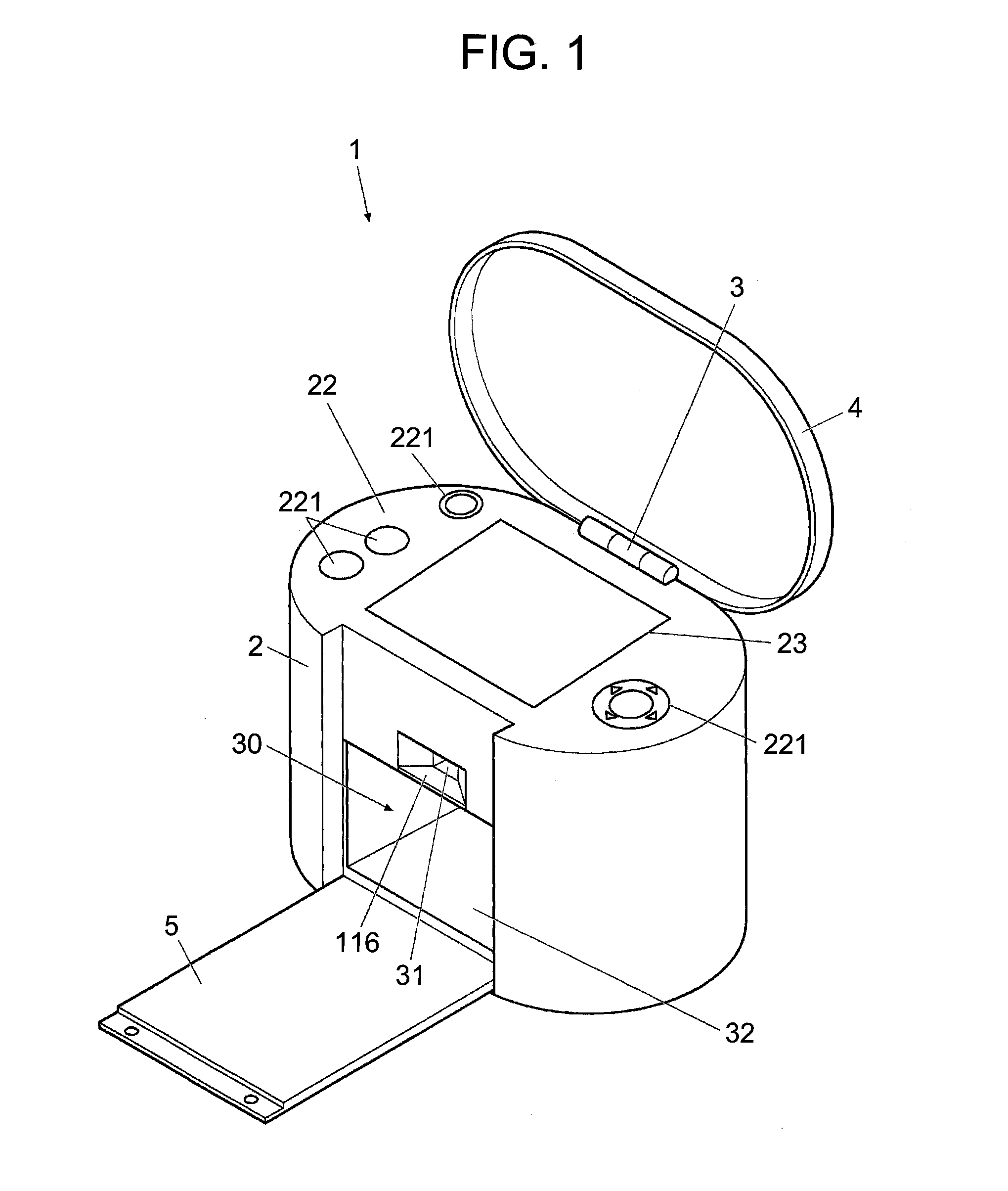
[0037]FIG. 1 is a perspective view showing the appearance of the nail printing apparatus in the present embodiment.

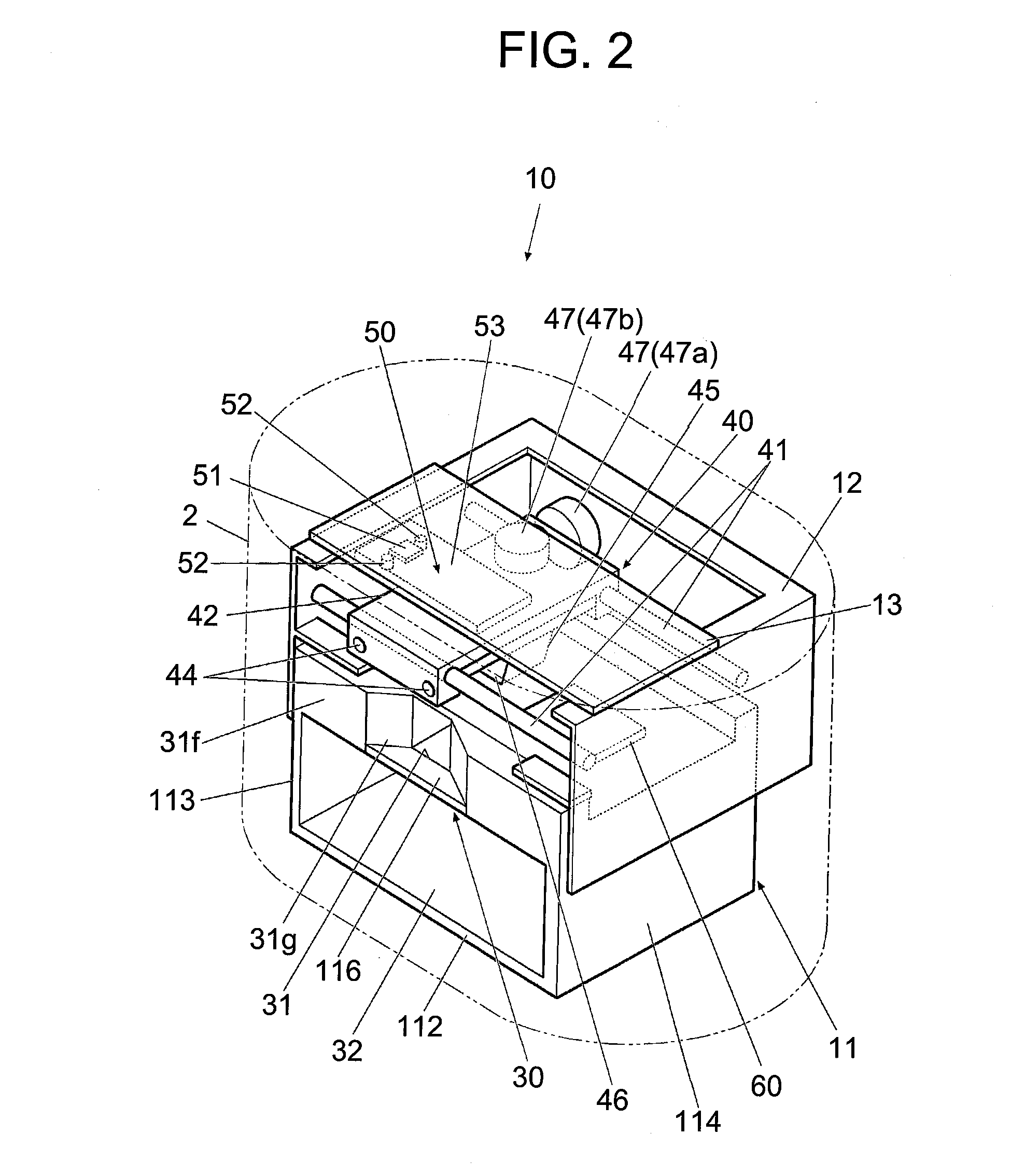
[0038]FIG. 2 is a perspective view showing the interior construction of the nail printing apparatus.

[0039]The nail printing apparatus 1 includes a case body 2 and a cover 4 as shown in FIG. 1.

[0040]The cover 4 is rotatably connected with the case body 2 with a hinge 3 disposed at the rear end of the upper surface (top board) of the case body 2.

[0041]The cover 4 is rotatable about the hinge 3 between the position where the cover 4 overlaps the top board of the case body 2 and the position where the cover 4 stands upright with respect to the top board of the case body 2 (see FIG. 1).

[0042]The case body 2 is formed to be substantially oval in a planar view.

[0043]At the front side of the case body 2, an open-and-close plate 5 is provided to be able to r...

second embodiment

[0198]Next, a nail printing apparatus in a second embodiment of the present invention is described with reference to FIGS. 9 to 12.

[0199]The second embodiment is different from the first embodiment only in the structure of a finger fixation section of the nail printing apparatus. Therefore, the following description is focused on the difference between the embodiments.

[0200]FIG. 9 is a perspective view conceptually showing the main body of a nail printing apparatus in the second embodiment.

[0201]FIG. 10 is a front view of the main body of the nail printing apparatus shown in FIG. 9.

[0202]FIG. 11 is a cross-sectional view, along the line XI-XI, shown in FIG. 10 viewed from the direction of the arrows.

[0203]As shown in FIGS. 9 to 11, the nail printing apparatus in the second present embodiment is provided with a finger fixation section 90 in a lower machine casing 11 in the same manner as the first embodiment.

[0204]In the present embodiment, the finger fixation section 90 is constitut...


PUM


Abstract

A nail printing apparatus to perform printing on a nail includes an imaging device, an illuminating device, a printing section and a movement mechanism. The imaging device photographs a specific finger including the nail to be printed from a plurality of directions different from each other and acquires a plurality of nail images of the nail. The illuminating device is disposed at a certain position relative to the imaging device and illuminates the nail when the imaging device photographs the nail. The printing section performs the printing on the nail. The movement mechanism moves the imaging device, the illuminating device and the printing section together with one another.

Description

CROSS-REFERENCE TO RELATED APPLICATIONS[0001]This application is based upon and claims the benefit of priority from the prior Japanese Patent Applications No. 2012-195735 filed on Sep. 6, 2012 and No. 2013-150332 filed on Jul. 19, 2013, the entire contents of which are incorporated herein by reference.BACKGROUND OF THE INVENTION[0002]1. Field of the Invention[0003]The present invention relates to a nail printing apparatus.[0004]2. Description of the Related Art[0005]A nail printing apparatus which is a printer to apply colors and / or designs on finger nails of a person has been known and is disclosed in, for example, Japanese Unexamined Patent Application Publication (Translation of PCT Application) No. 2003-534083.[0006]Such a nail printing apparatus needs to detect the shape of a finger nail to be printed, for example, in order to identify a region to be printed.[0007]Therefore, the nail printing apparatus is provided with an imaging device (camera) to photograph a nail to detect a...

Claims


Application Information

Patent Timeline
IPC IPC(8): A45D29/00
CPCA45D29/004A45D29/00B41J3/407A45D2029/005
Inventor BITOH, HIROYASU
Owner CASIO COMPUTER CO LTD
Why Eureka
Try Eureka