
Measurement of signal generated by contact of input device with surface

a technology of input device and surface, which is applied in the field of measurement of signals generated, can solve the problems of inability to duplicate unauthorized signatures, difficulties in unauthorized duplication of signatures, and inability to meet the needs of users, and achieve the effect of reliable and robust approach

Inactive Publication Date: 2014-03-06
TEN ONE DESIGN
View PDF12 Cites 11 Cited by
  • Summary
  • Abstract
  • Description
  • Claims
  • Application Information

AI Technical Summary

Benefits of technology

The invention provides a reliable and strong way to measure signals caused by pressing a device against a surface that has electrical activity. It uses a flexible and resilient conductive tip and a grounding and measuring circuit, which makes it easy to measure the signal. This method is durable and requires minimal maintenance. The invention is also adaptable to different types of electrically active surfaces, making it highly versatile. Additionally, it is cost-effective compared to other methods.

Problems solved by technology

These advances are beyond the capabilities of pencil and paper.
Force-measurement can also be the basis for validating the authenticity of a signature, insofar as capturing and storing force-measurement data makes unauthorized duplication of a signature more difficult.
Conventional technologies, however, suffer from certain drawbacks and limitations.
For instance, conventional pressure-sensing pen technologies may: require a mechanical actuator within the pressure-sensing device, which can lead to mechanical failure or be unhelpfully consumptive of room within an enclosure (pen body) that is generally very space-constrained; require precisely formed physical components that can have a high cost; under some circumstances (such as when drawing with a paintbrush), be unsuited to measure the interaction with a drawing surface, due to insensitivity (by way of example, a user may want to draw by lightly touching a drawing surface with the brush, but little or no pressure would be registered by a conventional sensor; or a user may want to draw a thick line by contacting the drawing surface with the side of the paintbrush bristles, but again little or no pressure would be registered by a conventional sensor).

Method used


Image

  • Measurement of signal generated by contact of input device with surface
  • Measurement of signal generated by contact of input device with surface
  • Measurement of signal generated by contact of input device with surface

Examples


Embodiment Construction

[0022]In various technologies, the mechanism for detecting force (or pressure) is self-contained. That is, the mechanism would work equally well pressed against a non-active surface as it would against, for instance, a computer display or active digitizing surface. Although in some cases, the active digitizing surface provides power to the stylus, so the assemblage would not work as intended outside of that environment, this is only because the necessary proper power to operate is missing.

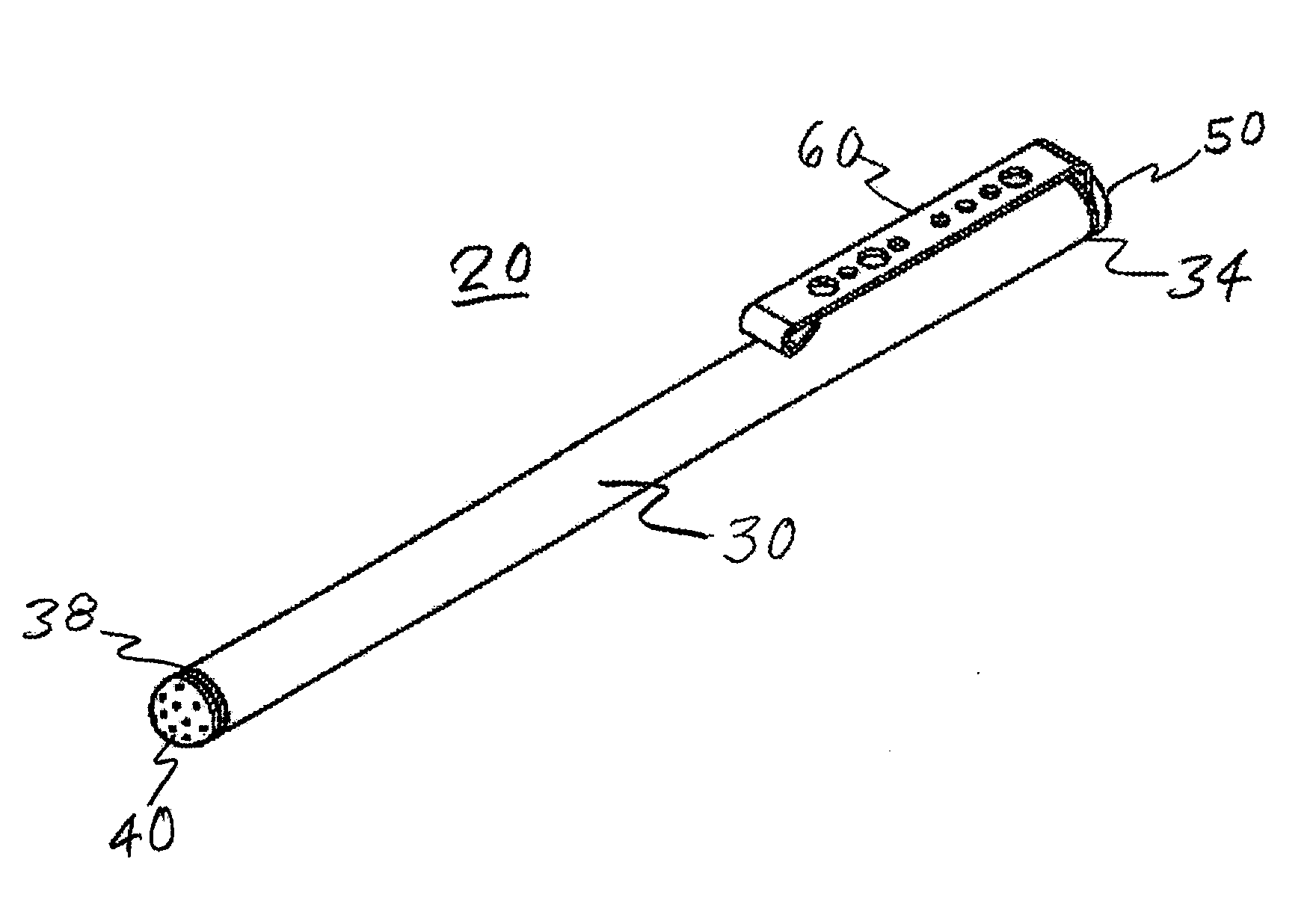
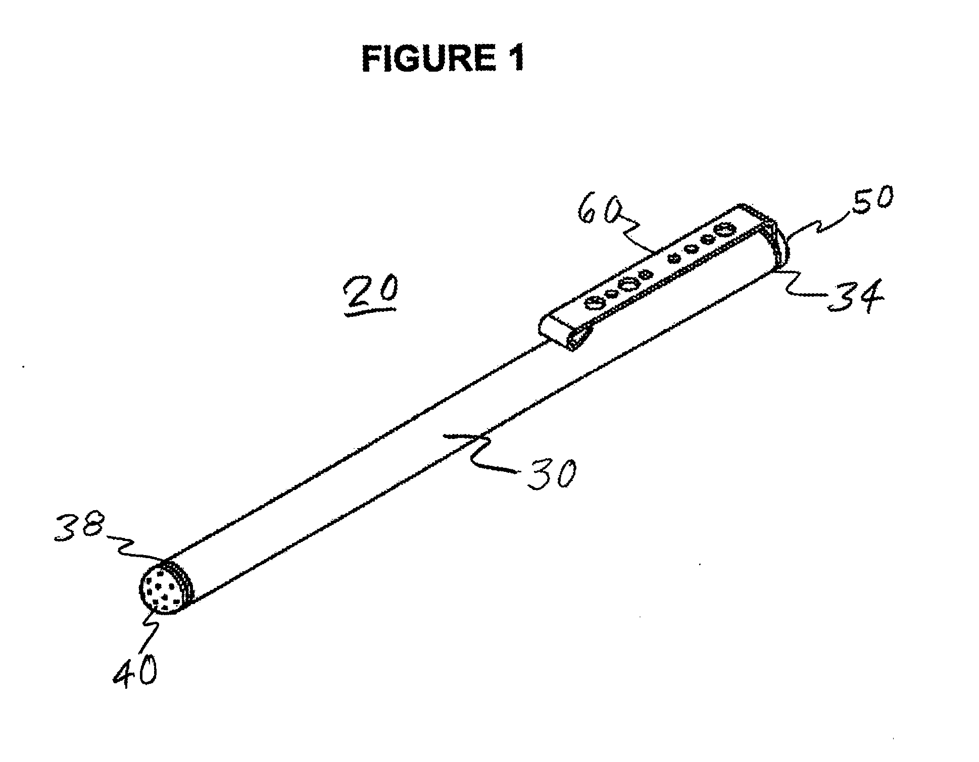
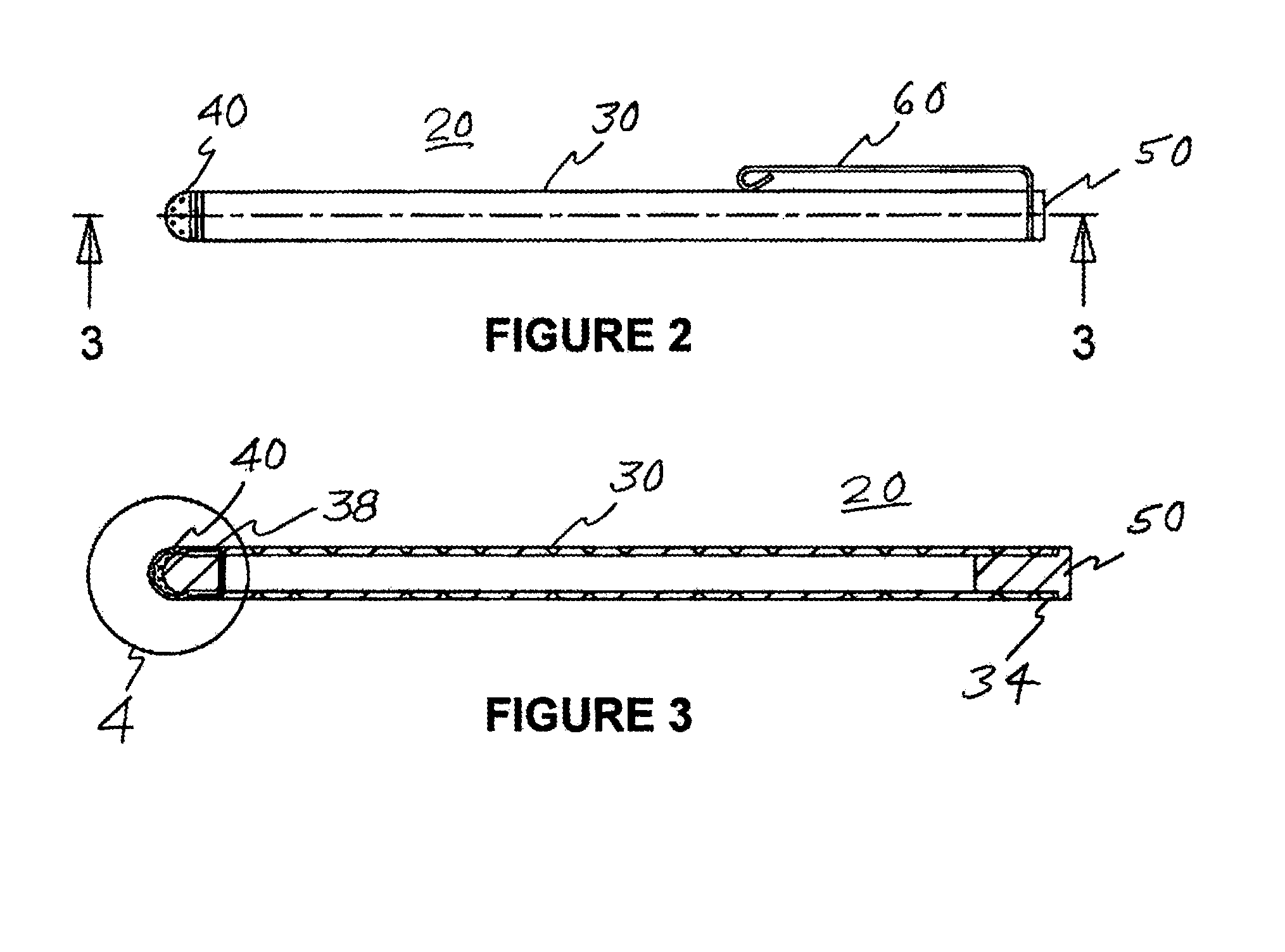
[0023]The present invention is a system and method of measuring a signal as aforesaid, and optionally determining by inference therefrom some further parameters such as the force (or pressure) exerted on a device urged against an electrically active surface member to produce the signal, typically a signal generated by capacitive coupling of those two components. Thus, the present invention involves as key elements a conductive or semi-conductive flexible tip material for contact with the surface me...


PUM


Abstract

A system for measurement of a signal generated through interaction between a device and an electrically active surface member wherein a flexible conductive tip element supported by the device's body, when in contact with or proximity of the electrically active surface member, gives rise to a signal which is variable as a function of the contact area between the tip element and the surface member or of the proximity of the tip element to the surface member, and wherein there is circuitry to afford a grounding path for the flexible conductive tip element and to measure the signal; and further a method for measuring a signal resulting from such interaction.

Description

FIELD OF THE INVENTION[0001]The present invention concerns the measurement of a signal generated by contact between a flexible electrically conductive or semi-conductive element and an electrically active surface member, such as the user interface (screen) for a tablet personal computer or hand-held data processing device.BACKGROUND OF THE INVENTION[0002]Devices with electrically-sensitive user interfaces are becoming increasingly popular because they accommodate the incorporation of familiar pencil-and-paper functions into a user's interaction with the device. By way of example, a tablet personal computer allows a user to interact with the computer by writing on it, without sacrificing the power or utility of its operating system and / or various desktop applications. Simply put, users are able to take notes in their own handwriting, similar to taking handwritten notes with a pencil and paper, while still realizing the benefits of computerization. Moreover, users are able to interact...

Claims


Application Information

Patent Timeline
Patent Type & Authority Applications(United States)
IPC IPC(8): G06F3/0354
CPCG06F3/03545
Inventor SKINNER, PETER JAMES
Owner TEN ONE DESIGN
Learn More