Method for balancing frequency instability on an electric grid using networked distributed energy storage systems

a technology of energy storage system and frequency instability, which is applied in the integration of power network operation system, load forecasting in ac network, secondary cell servicing/maintenance, etc., can solve the problems of high energy cost for users, high cost of energy storage medium, especially battery energy storage,

Active Publication Date: 2014-03-13
STEM
View PDF3 Cites 109 Cited by
  • Summary
  • Abstract
  • Description
  • Claims
  • Application Information

AI Technical Summary

Benefits of technology

[0016]Embodiments of the invention may further provide a method of controlling energy transferred between an electric grid and an electric load location comprises monitoring a first rate of energy transfer from an electric power line to the electric load location, wherein the electric power line is coupled to an electric meter adapted to determine power transferred between the electric load

Problems solved by technology

The cost to a utility for generating or purchasing electrical energy increases dramatically during periods of peak use versus periods of off-peak usage.
The higher rates charged during peak usage periods can lead to significantly higher energy costs for the user, especially when the user's period(s) of high demand coincides with or falls within the interval set by the utility as peak hours.
Energy storage mediums, especially battery energy storage, are expensive and, while various techniques are known by which an energy storage system can be used to optimize energy use at a business or home, such techniques are generally inefficient in applying stored energy to effectively control the energy use at an electric load location.
Consequently, an imprac

Method used


Image

  • Method for balancing frequency instability on an electric grid using networked distributed energy storage systems
  • Method for balancing frequency instability on an electric grid using networked distributed energy storage systems
  • Method for balancing frequency instability on an electric grid using networked distributed energy storage systems

Examples


Embodiment Construction

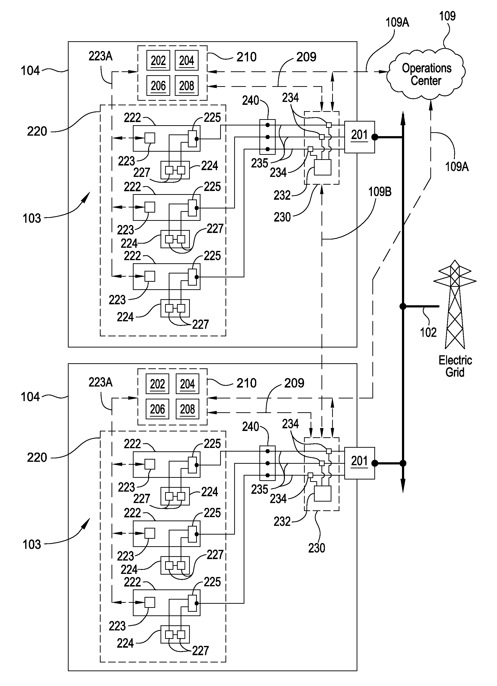
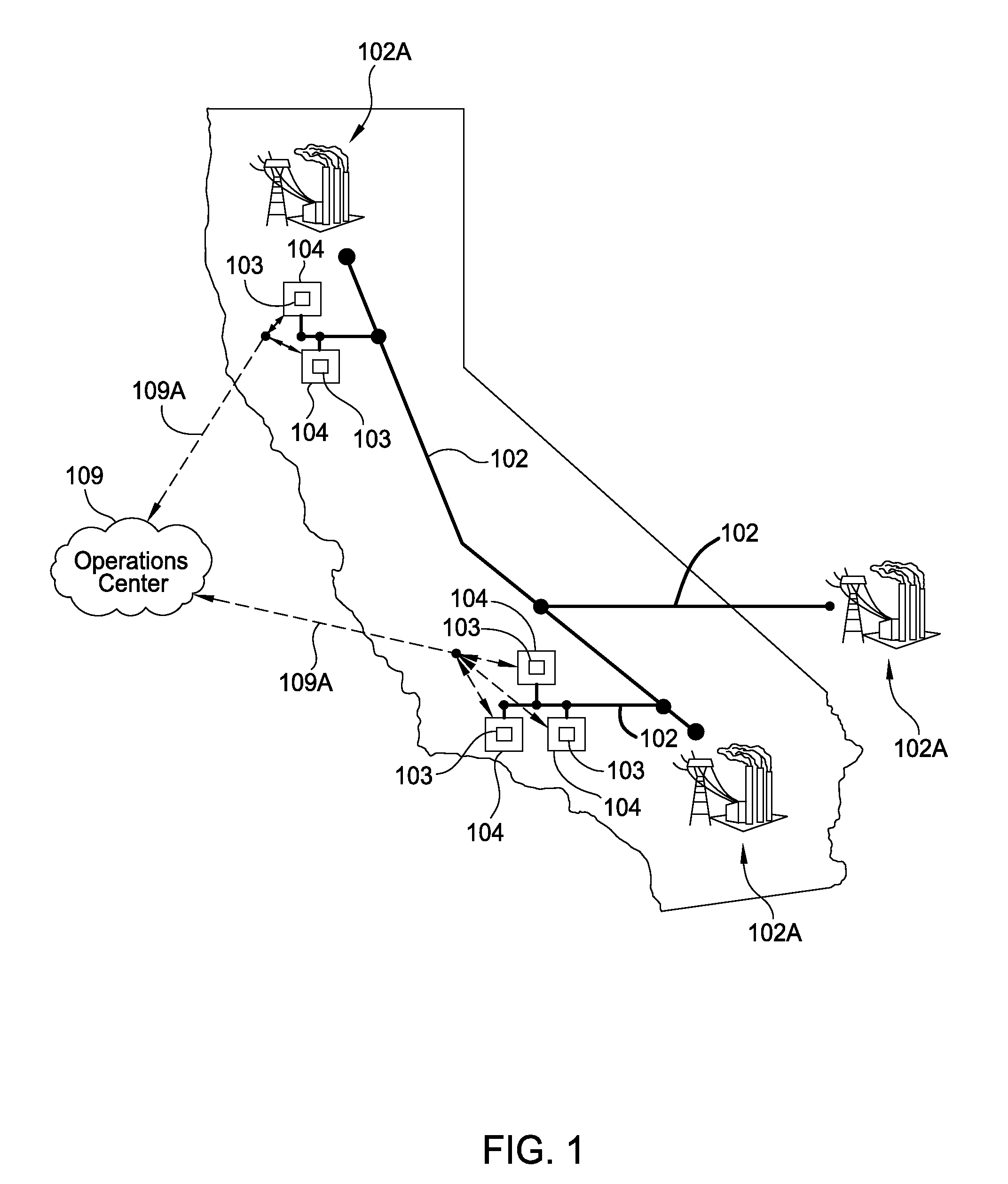
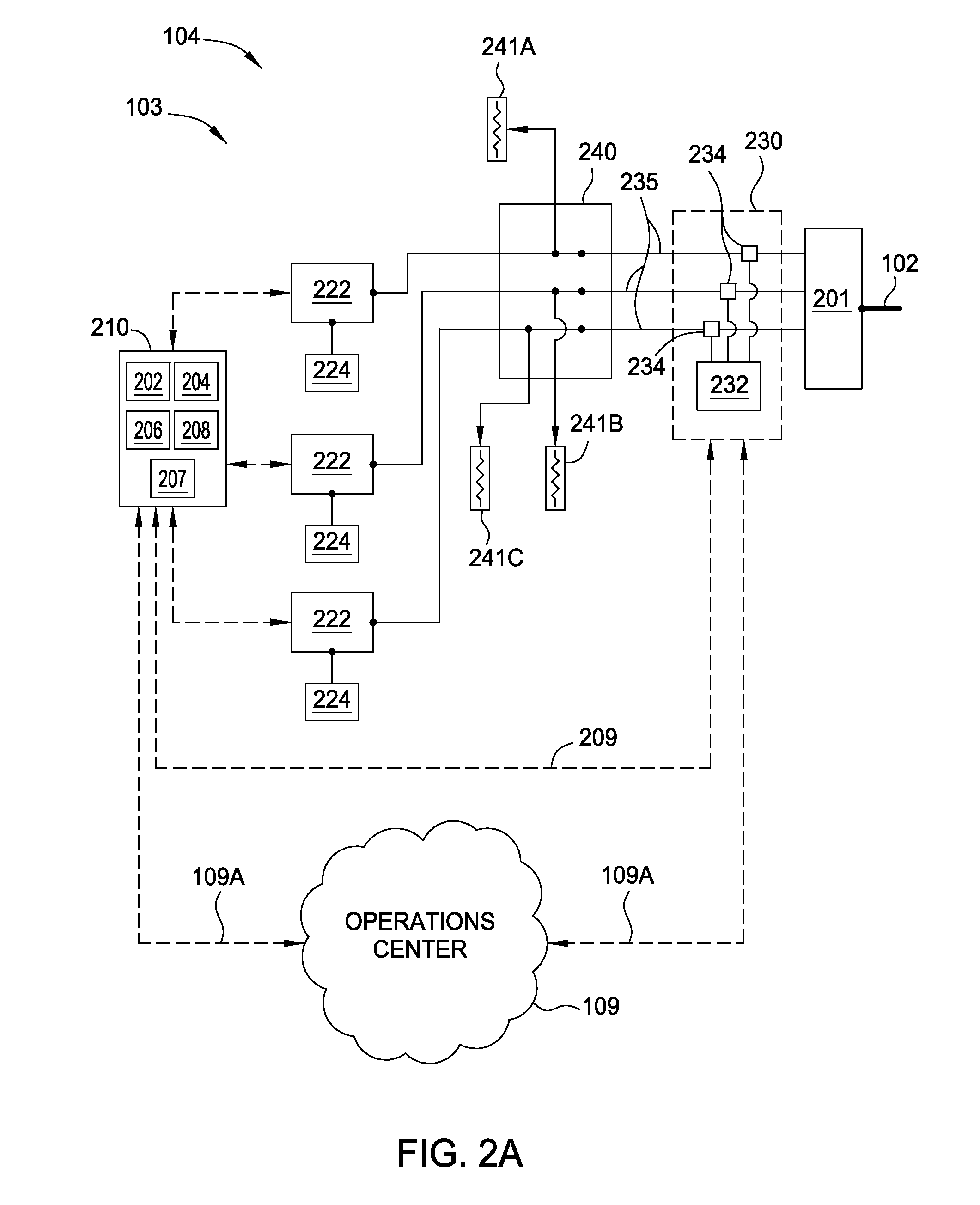
[0045]Embodiments of the present invention include control methods employed in multiphase distributed energy storage systems that are located behind utility meters typically located at, but not limited to, medium and large commercial and industrial locations and / or are connected along various parts of an electric grid. These distributed energy storage systems can operate semi-autonomously, but each may be in frequent contact with a cloud-based optimization engine that is configured to develop energy control solutions based on various data inputs and to communicate these energy control solutions to the distributed energy storage systems. Each installed distributed energy storage system can be used to monitor or receive information about the electricity use at its specific location and information relating to the power transmission on the electric grid. In an effort to control the local demand, the distributed energy storage system can discharge at times of high demand peaks in order ...


PUM


Abstract

Embodiments of the present invention include control methods employed in multiphase distributed energy storage systems that are located behind utility meters typically located at, but not limited to, medium and large commercial and industrial locations. These distributed energy storage systems can operate semi-autonomously, and can be configured to develop energy control solutions for an electric load location based on various data inputs and communicate these energy control solutions to the distributed energy storage systems. In some embodiments, one or more distributed energy storage systems may be used to absorb and/or deliver power to the electric grid in an effort to provide assistance to or correct for power transmission and distribution problems found on the electric grid outside of an electric load location. In some cases, two or more distributed energy storage systems are used to form a controlled and coordinated response to the problems seen on the electric grid.

Description

CROSS-REFERENCE TO RELATED APPLICATIONS[0001]This application claims the benefit of U.S. Provisional Patent Application Ser. No. 61 / 700,840, filed Sep. 13, 2012 [Atty. Dkt No. STEM / 0012L] and U.S. Provisional Patent Application Ser. No. 61 / 801,274, filed Mar. 15, 2013 [Atty. Dkt No. STEM / 0016L], which are all hereby incorporated herein by reference.BACKGROUND OF THE INVENTION[0002]1. Field of the Invention[0003]Embodiments of the present invention generally relate to a method and an apparatus for controlling fluctuations in power and amount of power used at an electric load location and / or on an electrical grid.[0004]2. Description of the Related Art[0005]Energy demand at a commercial site, such as a business, or at home will vary over the time of day. In a typical home or hotel setting, there is a peak in the morning when the occupants get up and when the occupants return home at the end of the day. This typically creates two demand peaks during a normal day. Commercial buildings t...

Claims


Application Information

Patent Timeline
IPC IPC(8): H02J7/00
CPCH02J7/007H02J3/32Y04S20/12H02J2310/64H02J3/003H02J13/00017H02J13/00034Y02B90/20Y04S20/222Y04S40/124Y04S50/10Y02B70/3225H02J3/00H02J7/02
Inventor KEARNS, BENDETMERS, JAMES W.BURLINSON, JONSTEVENS, DREW
Owner STEM
Why Eureka
Try Eureka