Firestop collar

a technology of firestop and collar, which is applied in the field of firestop collar, can solve the problem that two work steps are necessary in order to cut them to size, and achieve the effect of convenient processing

Active Publication Date: 2014-03-20
HILTI AG
View PDF6 Cites 33 Cited by
  • Summary
  • Abstract
  • Description
  • Claims
  • Application Information

AI Technical Summary

Benefits of technology

[0005]It is an object of the present invention to provide a firestop collar whose size can be flexibly adapted and which can also be easily processed.

Problems solved by technology

A disadvantage of this strip, however, is that two work steps are necessary in order to cut them to size.

Method used


Image

  • Firestop collar
  • Firestop collar
  • Firestop collar

Examples


Embodiment Construction

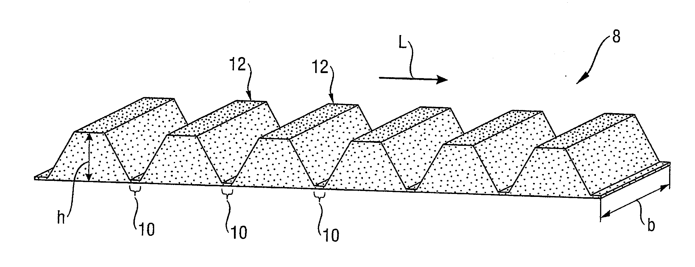
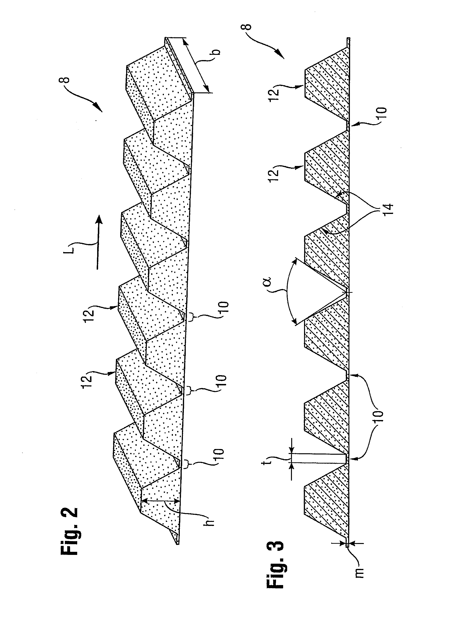
[0027]FIG. 2 shows a schematic perspective view of an intumescent strip 8 for a firestop collar 2 according to a first embodiment. The intumescent strip 8 has cutting areas 10 located between the blocks 12 that are at a distance from each other in the lengthwise direction L. The intumescent strip 8 in these cutting areas 10 is thinner than in the adjacent areas, which have a maximum thickness h. Preferably, the thickness m of the intumescent strip 8 in the cutting areas 10 is 5 mm at the maximum. The width t of the cutting areas 10 (also see FIG. 2) in the lengthwise direction L is at least 3 mm. The width b of the intumescent strip 8 is preferably between 20 mm and 100 mm. The maximum height h of the blocks 12 is preferably between 4 mm and 30 mm.

[0028]FIG. 3 shows a sectional view of the intumescent strip 8 known from FIG. 2. The minimum continuous band thickness m is dimensioned in such a way that the intumescent strip 8, together with a support band, forms a sufficiently sturdy ...


PUM


Abstract

A firestop collar including a support band made of sheet metal and an intumescent strip that runs along the support band and is connected to it. The support band is provided with several pre-defined cutting zones which are at a distance from each other in the lengthwise direction and which run crosswise to the lengthwise direction. The intumescent strip has cutting areas that are oriented in the same manner and in which the intumescent strip is thinner than it is in the adjacent areas in the lengthwise direction. The cutting areas coincide with the cutting zones of the support band.

Description

[0001]This claims the benefit of German Patent Application DE 10 2011 083 035.9, filed Sep. 20, 2011 and hereby incorporated by reference herein.[0002]The present invention relates to a firestop collar comprising a support band made of sheet metal and an intumescent strip.BACKGROUND[0003]Firestop collars are arranged around pipes or cables that pass through a penetration in a wall or ceiling, and they comprise intumescent material that expands upon exposure to heat, closing the penetration as tightly as possible so as to prevent propagation of the fire. This situation is shown by way of an example in FIG. 1, which depicts a top view of a firestop collar 2 that is secured to a wall with anchors 4. In case of fire, the intumescent material contained in the firestop collar 2 expands (as indicated by the arrows) in the direction of the penetration through which a pipe 6 passes. Depending on the number and size of the pipes, cable harnesses, etc. present in a wall or ceiling penetration,...

Claims


Application Information

Patent Timeline
Patent Type & Authority Applications(United States)
IPC IPC(8): F16L57/04F16L5/04
CPCA62C2/065H02G3/0412F16L57/04H02G3/22F16L5/04
Inventor FOERG, CHRISTIAN
Owner HILTI AG
Why Eureka
Try Eureka