Overlay Navigation In User Interface

a user interface and overlay technology, applied in the field of overlay navigation in the user interface, can solve the problems of not being able to navigate between different parts of the process in a user-intuitive manner, the number of parts or components may be so large, and the user may not be able to use thumbnails in the user-intuitive manner, so as to achieve the effect of easy and quick navigation to the sub-ui

Active Publication Date: 2014-03-20
ABB (SCHWEIZ) AG
View PDF3 Cites 5 Cited by
  • Summary
  • Abstract
  • Description
  • Claims
  • Application Information

AI Technical Summary

Benefits of technology

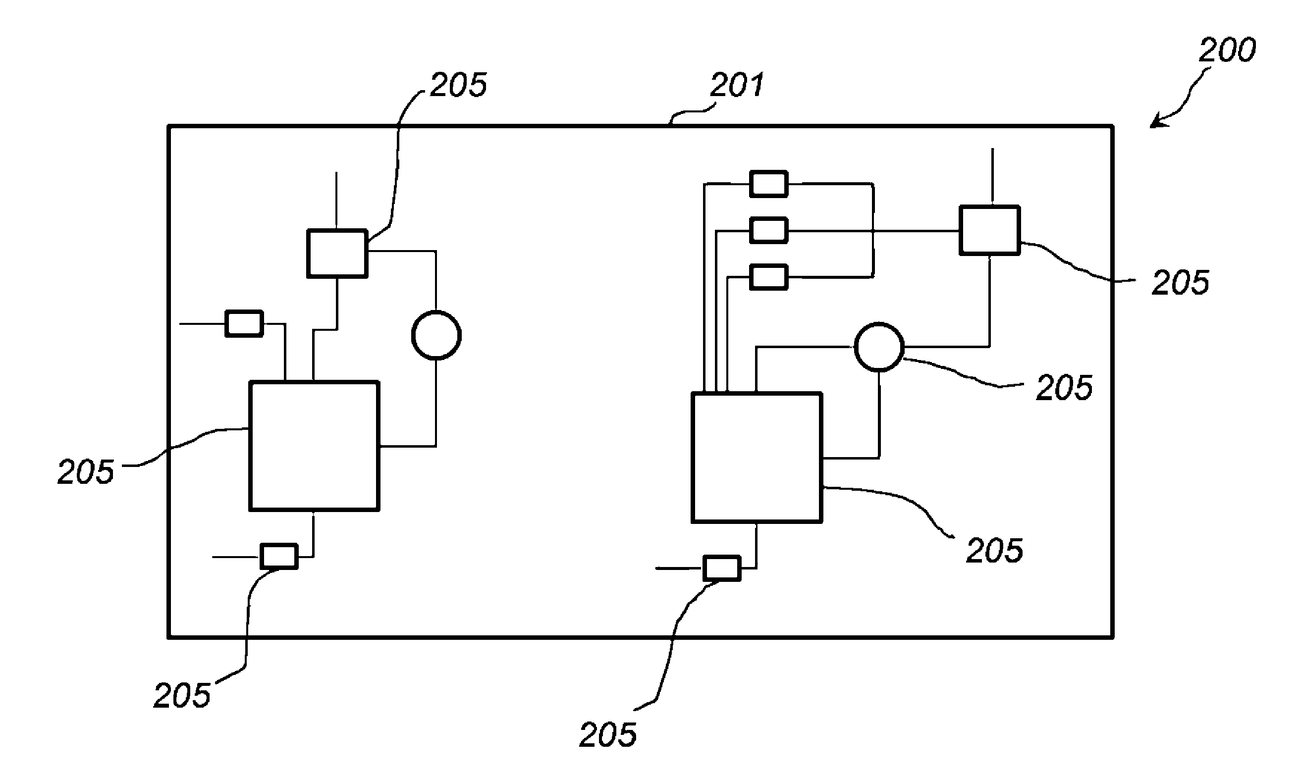
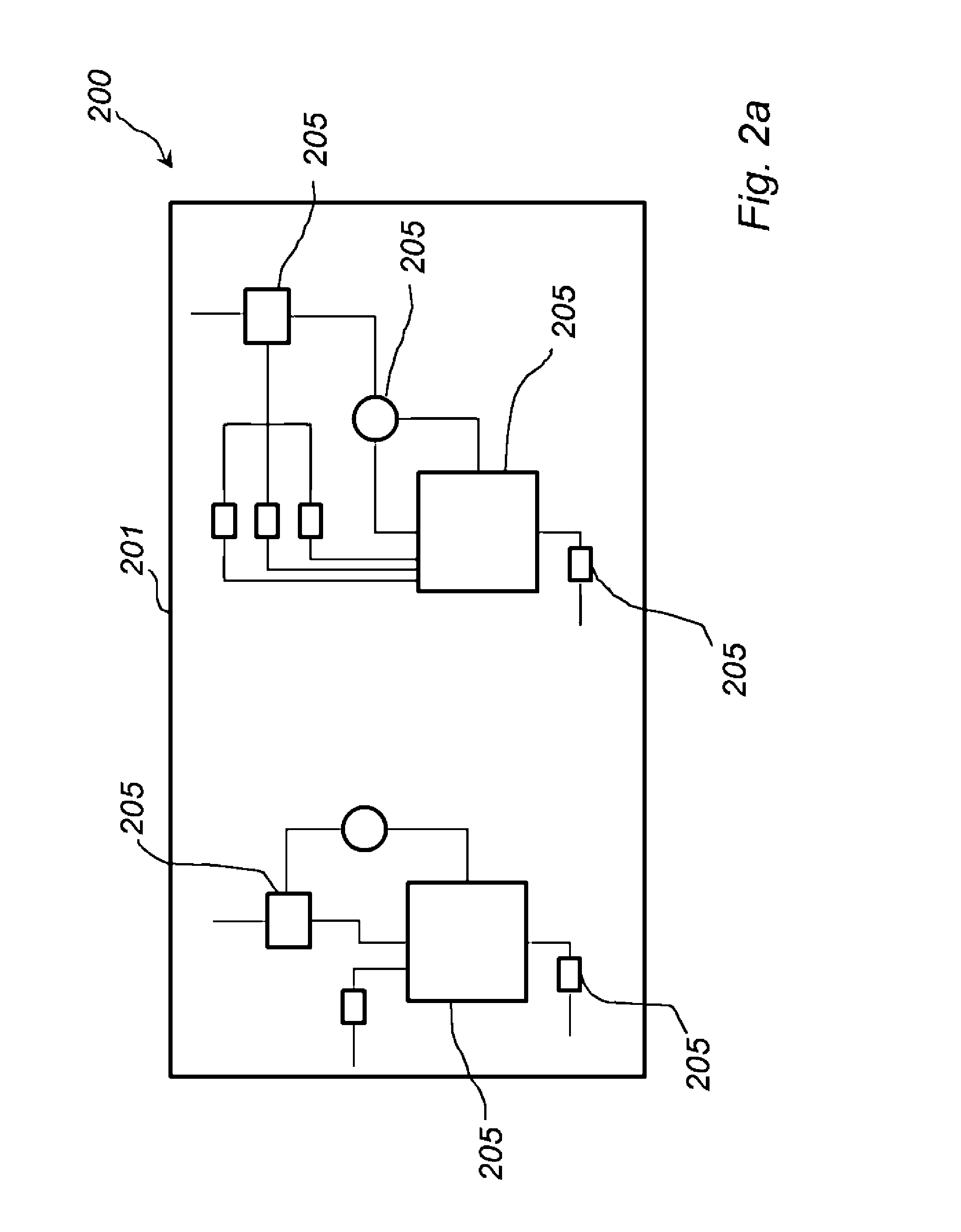
[0052]Thus, the visualization or visual representation of each sub-UI can be performed in such a manner that visual markers or indications of the components in the respective sub-UI replaces or supplements the process graphics of the actual components in the sub-UI, in such a way that the relative arrangement of the visual markers or indications in the visualization as displayed on the display screen corresponds to the relative arrangement of the components in the sub-UI as displayed on the display screen. In this way, the user or operator may by visually inspecting the visualization as displayed on the display screen readily recognize which sub-UI the visualization corresponds to.
[0053]The visualization can be performed in such a manner that the visual markers or indications of the components in the respective sub-UI can provide the user or operator with the operational status of the components in the sub-UI by visually inspecting the visualization as displayed on the display screen. In this way, the user may detect which part or parts of the process that require attention and relatively easily and quickly navigate to the sub-UI of that part or those parts of the process, by selecting the corresponding visualization or visual representation by means of the selection sub-UI.

Problems solved by technology

In some applications the number of parts or components in the process may be so large that all parts of the process cannot feasibly be shown to the user via a single UI at a time, for example in a single graphic window displayed on a display screen displaying process graphics.
Hence, several UIs, or sub-UIs, i.e. UIs that are encompassed by or comprised in another ‘main’ UI, may be required in order to enable controlling and / or monitoring the entire process, but all of these UIs may not feasibly fit within the display screen at the same time.
However, even with the provision of such thumbnails, there is generally no user-intuitive manner in which the operator can navigate between different parts of the process using thumbnails that is consistent for different applications, e.g., control systems for different industrial processes.
The navigation between different parts of the process in the UI of the process control system may accordingly become time-consuming and / or frustrating for the user.
It may become difficult for a user to get an adequate overview of the entire process since all of the thumbnails may not be displayed at the same time and / or in the same display.
However, reducing the size of a UI comprising a graphic window on the display screen may result in a thumbnail comprising a relatively small graphic object that is cluttered with graphics objects.
This may make it difficult for the user to recognize any distinctive pattern in the thumbnail for recognizing which part or parts of the process that are indicated in the UI that corresponds to the thumbnail.

Method used


Image

  • Overlay Navigation In User Interface
  • Overlay Navigation In User Interface
  • Overlay Navigation In User Interface

Examples


Embodiment Construction

[0071]The present invention will now be described more fully hereinafter with reference to the accompanying drawings, in which exemplifying embodiments of the present invention are shown. This present invention may, however, be embodied in many different forms and should not be construed as limited to the embodiments set forth herein; rather, these embodiments are provided by way of example so that this disclosure will convey the scope of the invention to those skilled in the art. Furthermore, like numbers refer to like or similar elements or components throughout. The steps of any method disclosed herein do not have to be performed in the exact order disclosed, unless explicitly stated.

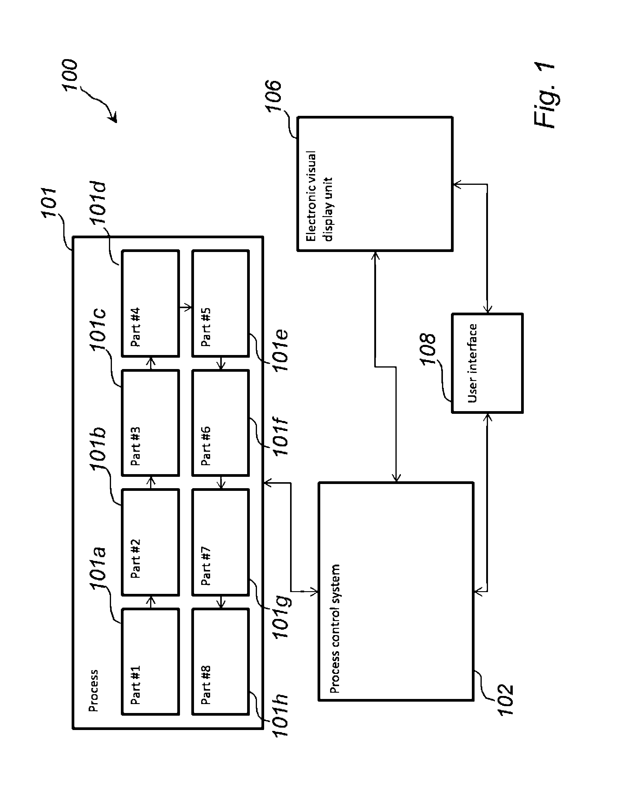
[0072]Referring now to FIG. 1, there is shown a schematic block diagram of a system 100 in accordance with an exemplifying embodiment of the present invention.

[0073]The system 100 comprises a process 101 comprising several parts, sub-processes, or steps 101a-101f. Each part 101a-101f may refer to a s...


PUM


Abstract

A user interface (UI) for a process control system is disclosed. The UI is configured to be displayed on an electronic visual display unit connectable to the process control system. The UI includes a plurality of sub-UIs, each sub-UI being adapted to visually indicate at least a part of a process controlled by the process control system. A selection sub-UI is provided that can be selectively activated and deactivated by the user or operator, which selection sub-UI enables the user to at least temporarily select one or more of a plurality of visual representations corresponding to corresponding ones of the plurality of sub-UIs. When the selection sub-UI is deactivated, sub-UI corresponding to the selected one or more of the plurality of visual representations is displayed on the display unit.

Description

FIELD OF THE INVENTION[0001]The present invention generally relates to process control systems. Specifically, the present invention relates to a user interface (UI) of a process control system and a method in a UI of a process control system for selectively displaying at least one of a plurality of sub-UIs on a display unit.BACKGROUND OF THE INVENTION[0002]In control systems for controlling and / or monitoring an industrial process, the operator typically controls / monitors the entire process or different parts of the process by means of one or more user interfaces (UIs), for example constituted by one or more graphic windows displayed on a display screen, each graphic window displaying process graphics. Such UIs may enable the operator to monitor the status of the different components of the process and / or control the operation of individual components of the process by means of user input provided to the UI. Providing user input to the UI may for example comprise providing instructio...

Claims


Application Information

Patent Timeline
Patent Type & Authority Applications(United States)
IPC IPC(8): G06F3/0484
CPCG06F3/0484G05B23/0267G05B2219/23136G05B2219/23163G05B2219/31472G05B2219/31474
Inventor OLAUSSON, MARTINTIMSJO, SUSANNE
Owner ABB (SCHWEIZ) AG
Why Eureka
Try Eureka