Zoom lens, image-pickup apparatus having the same, and image projection apparatus having the same

a technology of image-picking apparatus and zoom lens, which is applied in the direction of color television details, television systems, instruments, etc., can solve the problems of difficult to correct lateral chromatic aberration in a well-balanced manner, and achieve the effect of easy and proper correction of lateral chromatic aberration and high zoom ratio

Inactive Publication Date: 2014-03-27
CANON KK
View PDF4 Cites 26 Cited by
  • Summary
  • Abstract
  • Description
  • Claims
  • Application Information

AI Technical Summary

Benefits of technology

[0009]The present invention provides a zoom lens with a high zoom ratio and a wide angle of view, which can easily and properly correct the lateral chromatic aberration.

Problems solved by technology

At this time, the secondary spectra of the lateral chromatic aberrations occur at the wide-angle end and the telephoto end in opposite directions, and it becomes difficult to correct them in a well-balanced manner.

Method used


Image

  • Zoom lens, image-pickup apparatus having the same, and image projection apparatus having the same
  • Zoom lens, image-pickup apparatus having the same, and image projection apparatus having the same
  • Zoom lens, image-pickup apparatus having the same, and image projection apparatus having the same

Examples


first embodiment

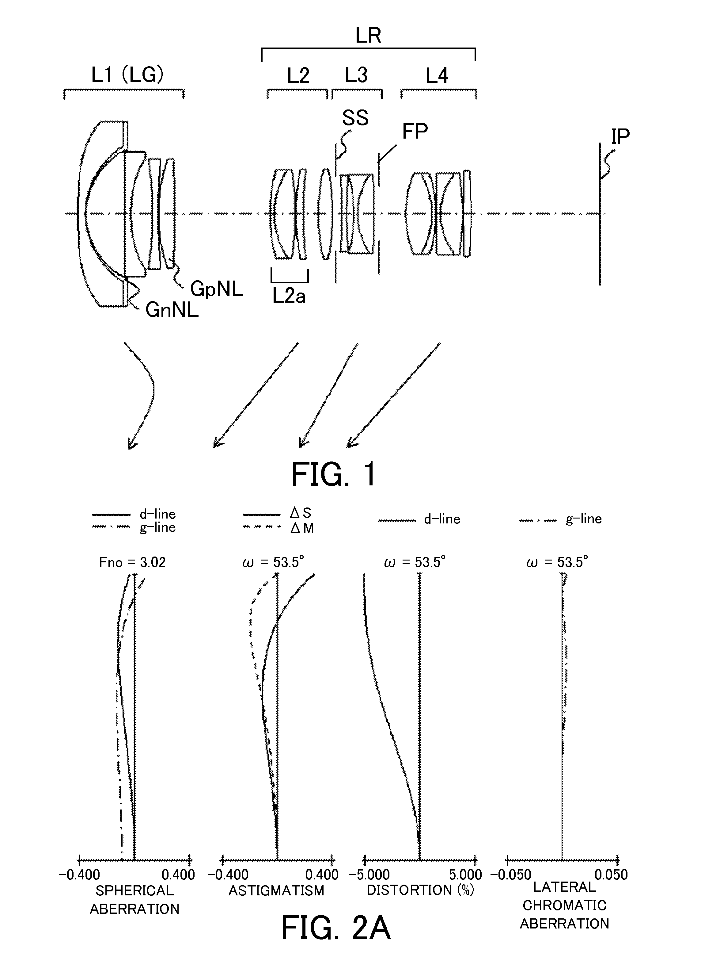
[0070]Referring now to FIG. 1, a zoom lens according to the first embodiment of the present invention will be described. The zoom lens of the first embodiment is a four-unit zoom lens which includes, in order from an object side to an image side, a first lens unit L1 having a negative refractive power, a second lens unit L2 having a positive refractive power, a third lens unit L3 having a negative refractive power, and a fourth lens unit L4 having a positive refractive power. The rear unit LR includes the second lens unit L2 to the fourth lens unit L4.

[0071]In the first embodiment, in zooming from the wide-angle end to the telephoto end, the lens unit L1 moves with a locus convex on the image side as illustrated by an arrow so as to compensate a fluctuation of an image plane caused by the magnification variation. The second lens unit L2, the third lens unit L3, and the fourth lens unit L4 are respectively magnification varying lens units, and move to the object side. The aperture di...

second embodiment

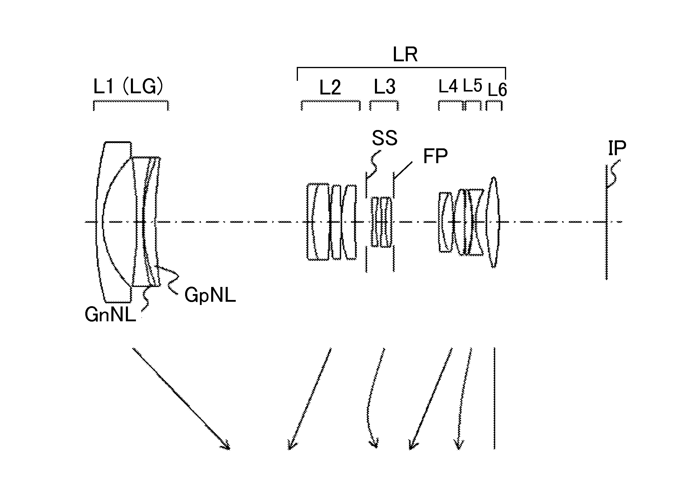
[0074]Referring now to FIG. 3, a description will be given of a zoom lens according to a second embodiment of the present invention. The zoom lens of the second embodiment is a six-unit zoom lens which includes, in order from an object side to an image side, a first lens unit L1 having a negative refractive power, a second lens unit L2 having a positive refractive power, a third lens unit L3 having a negative refractive power, a fourth lens unit L4 having a positive refractive power, a fifth lens unit L5 having a negative refractive power, and a sixth lens unit L6 having a positive refractive power. The rear unit LR includes the second lens unit L2 to the sixth lens unit L6.

[0075]In the second embodiment, in zooming from the wide-angle end to the telephoto end, the lens unit L3 moves with a locus convex on the image side as illustrated by an arrow so as to compensate a fluctuation of an image plane caused by the magnification variation. The first lens unit L1 is a magnification vary...

third embodiment

[0079]Referring now to FIG. 5, a description will be given of a zoom lens according to a third embodiment of the present invention. The zoom lens of the third embodiment takes the same zoom-type and the focusing-type as those of the second embodiment illustrated in FIG. 3. The third embodiment differs from the second embodiment in arrangement of the optical element GnNL, and in lens shape in each lens unit.

[0080]In the third embodiment, the optical element GnNL having a negative refractive power which satisfies the conditional expressions (1) and (2) is disposed at the second lens unit L2. More specifically, the optical element GnNL is a part of a three-piece cemented lens in which the optical element GnNL is sandwiched and cemented with a negative lens and a positive lens in the second lens unit L2. The optical element GnNL is disposed at the second lens unit L2 where the pupil paraxial ray and the object paraxial ray are high at the wide-angle end. Thereby, the secondary lateral c...


PUM


Abstract

The zoom lens includes, in order from an object side to an image side, a first lens unit having a negative refractive power, a rear unit including one or more lens units, a distance between every adjacent lens units varies during zooming, and an aperture diaphragm on the image side of the first lens unit, a combined focal length of the rear unit at a wide-angle end being positive. One lens unit LG on the object side of the aperture diaphragm is made of a solid material, and includes an optical element GnNL having a negative refractive power and another optical element having a positive refractive power, and the predetermined conditions are satisfied.

Description

BACKGROUND OF THE INVENTION[0001]1. Field of the Invention[0002]The present invention is suitable for an image-pickup optical system, for example, for a digital camera, a video camera, a film-based camera, a TV camera, and the like, and for a projection optical system for a projector.[0003]2. Description of the Related Art[0004]An image-pickup optical system for a digital camera and a projection optical system for a liquid crystal projector are required to have a wide angle of view, a high zoom ratio, and a high optical performance in the entire zoom range. As a zoom lens which can easily widen an angle of view, a negative-lead type zoom lens is known which includes a first lens unit that is arranged closest to the object and has a negative refractive power.[0005]As the angle of view is widened in the negative-lead type zoom lens, the secondary (spectrum of the) lateral chromatic aberration increases at the wide-angle end. As the zoom ratio is enlarged with widening the angle of vie...

Claims


Application Information

Patent Timeline
Patent Type & Authority Applications(United States)
IPC IPC(8): G02B15/14H04N5/232
CPCH04N5/23296G02B15/14G02B13/18G02B15/177G02B15/1425H04N23/69
Inventor TASHIRO, YOSHIHISAHIASA, NORIHITO
Owner CANON KK
Why Eureka
Try Eureka