Zoom lens, image-pickup apparatus having the same, and image projection apparatus having the same
a technology of image-picking apparatus and zoom lens, which is applied in the direction of color television details, television systems, instruments, etc., can solve the problems of difficult to correct lateral chromatic aberration in a well-balanced manner, and achieve the effect of easy and proper correction of lateral chromatic aberration and high zoom ratio
- Summary
- Abstract
- Description
- Claims
- Application Information
AI Technical Summary
Benefits of technology
Problems solved by technology
Method used
Image
Examples
first embodiment
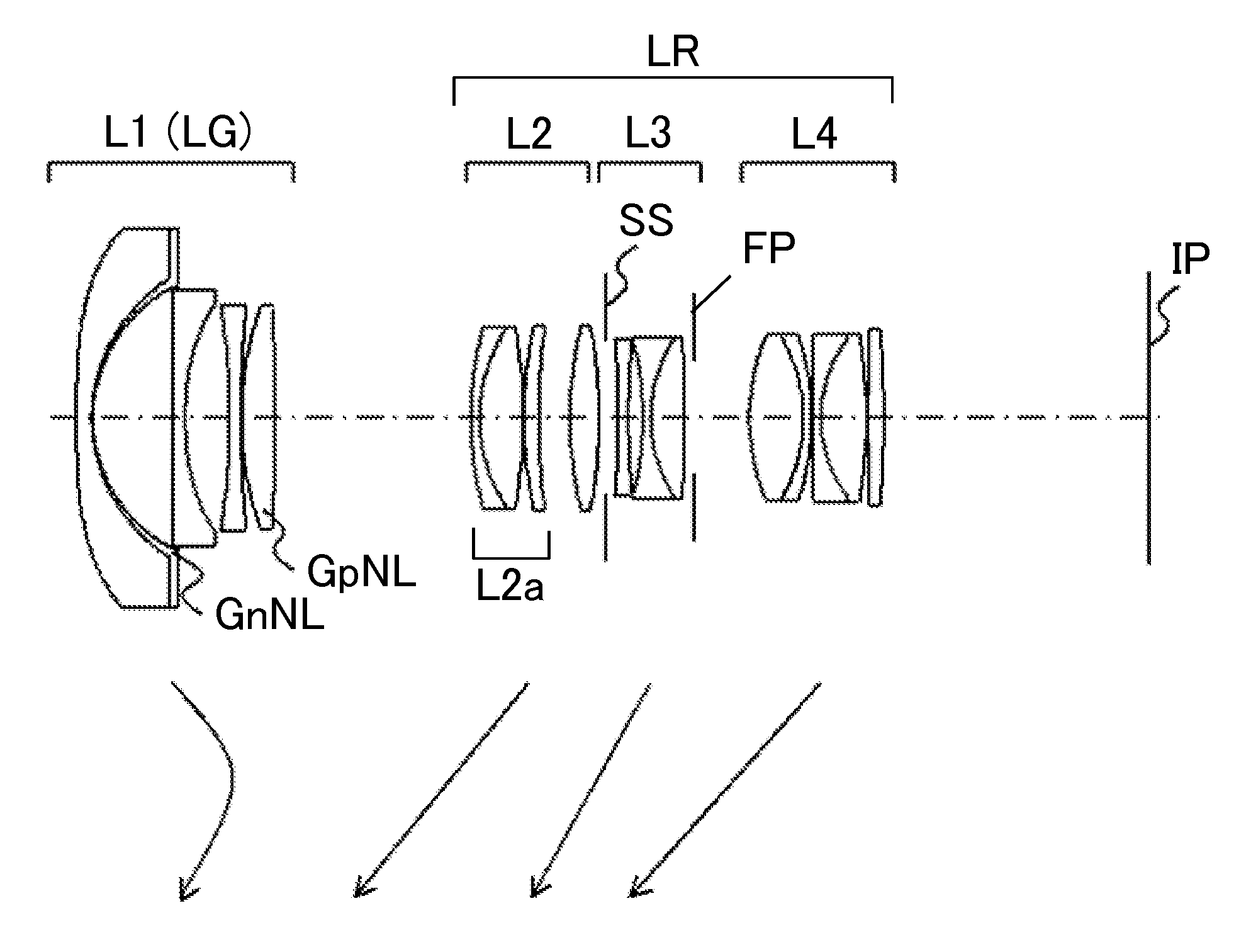
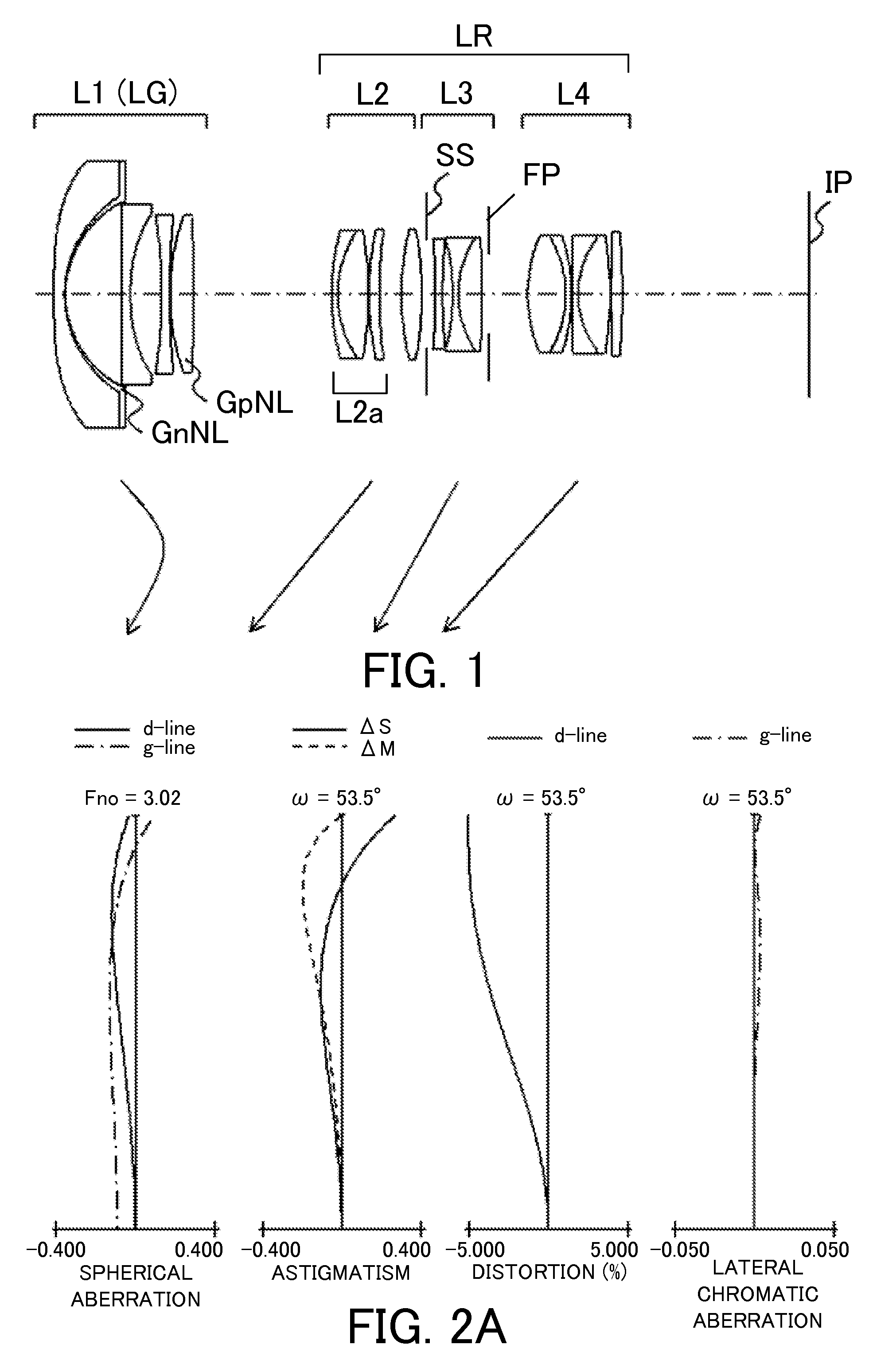
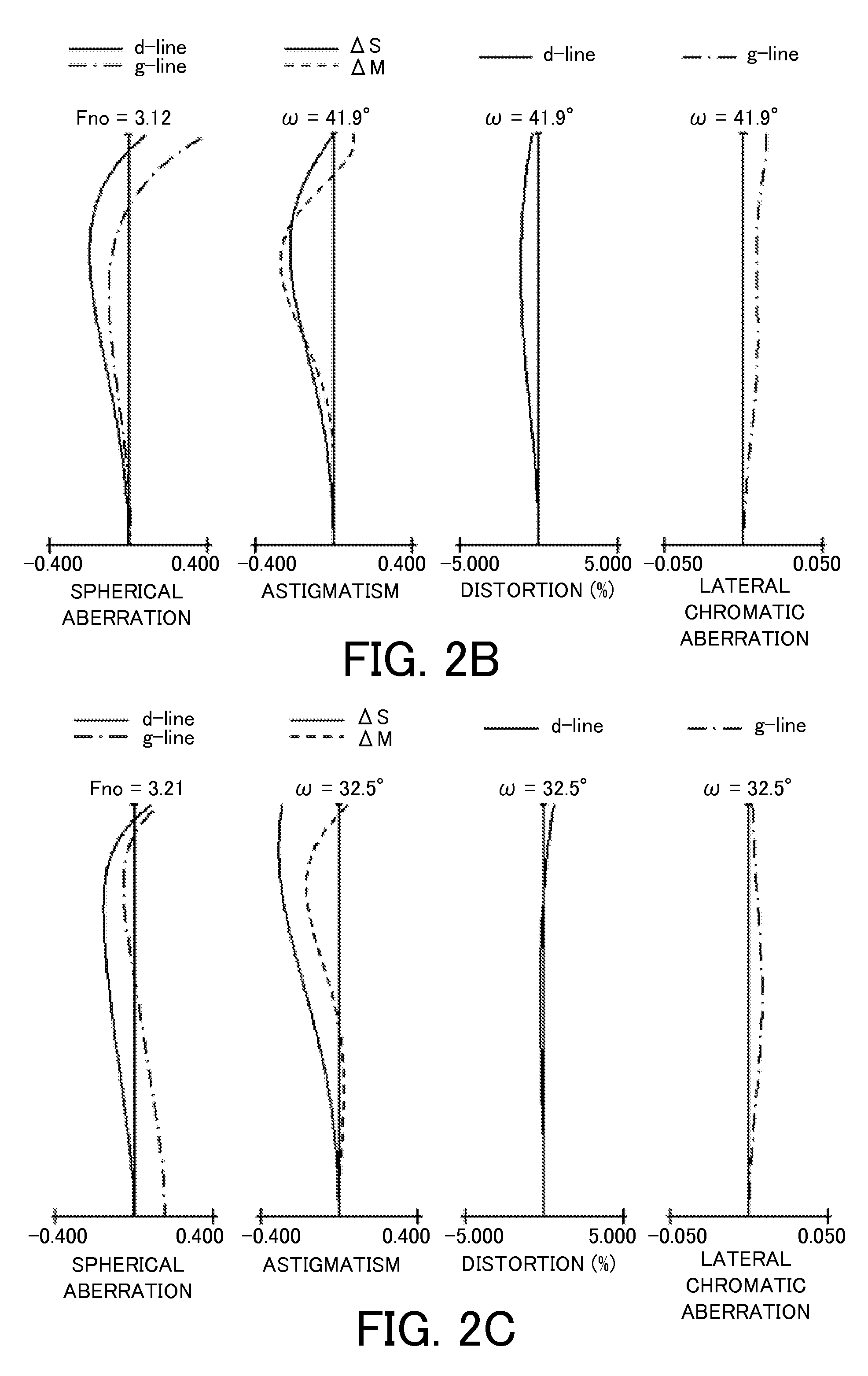
[0070]Referring now to FIG. 1, a zoom lens according to the first embodiment of the present invention will be described. The zoom lens of the first embodiment is a four-unit zoom lens which includes, in order from an object side to an image side, a first lens unit L1 having a negative refractive power, a second lens unit L2 having a positive refractive power, a third lens unit L3 having a negative refractive power, and a fourth lens unit L4 having a positive refractive power. The rear unit LR includes the second lens unit L2 to the fourth lens unit L4.
[0071]In the first embodiment, in zooming from the wide-angle end to the telephoto end, the lens unit L1 moves with a locus convex on the image side as illustrated by an arrow so as to compensate a fluctuation of an image plane caused by the magnification variation. The second lens unit L2, the third lens unit L3, and the fourth lens unit L4 are respectively magnification varying lens units, and move to the object side. The aperture di...
second embodiment
[0074]Referring now to FIG. 3, a description will be given of a zoom lens according to a second embodiment of the present invention. The zoom lens of the second embodiment is a six-unit zoom lens which includes, in order from an object side to an image side, a first lens unit L1 having a negative refractive power, a second lens unit L2 having a positive refractive power, a third lens unit L3 having a negative refractive power, a fourth lens unit L4 having a positive refractive power, a fifth lens unit L5 having a negative refractive power, and a sixth lens unit L6 having a positive refractive power. The rear unit LR includes the second lens unit L2 to the sixth lens unit L6.
[0075]In the second embodiment, in zooming from the wide-angle end to the telephoto end, the lens unit L3 moves with a locus convex on the image side as illustrated by an arrow so as to compensate a fluctuation of an image plane caused by the magnification variation. The first lens unit L1 is a magnification vary...
third embodiment
[0079]Referring now to FIG. 5, a description will be given of a zoom lens according to a third embodiment of the present invention. The zoom lens of the third embodiment takes the same zoom-type and the focusing-type as those of the second embodiment illustrated in FIG. 3. The third embodiment differs from the second embodiment in arrangement of the optical element GnNL, and in lens shape in each lens unit.
[0080]In the third embodiment, the optical element GnNL having a negative refractive power which satisfies the conditional expressions (1) and (2) is disposed at the second lens unit L2. More specifically, the optical element GnNL is a part of a three-piece cemented lens in which the optical element GnNL is sandwiched and cemented with a negative lens and a positive lens in the second lens unit L2. The optical element GnNL is disposed at the second lens unit L2 where the pupil paraxial ray and the object paraxial ray are high at the wide-angle end. Thereby, the secondary lateral c...
PUM
 Abstract
Description
Claims
Application Information
 - R&D
- Intellectual Property
- Life Sciences
- Materials
- Tech Scout
- Unparalleled Data Quality
- Higher Quality Content
- 60% Fewer Hallucinations
Browse by: Latest US Patents, China's latest patents, Technical Efficacy Thesaurus, Application Domain, Technology Topic, Popular Technical Reports.
© 2025 PatSnap. All rights reserved.Legal|Privacy policy|Modern Slavery Act Transparency Statement|Sitemap|About US| Contact US: help@patsnap.com


