Slim Lens Assembly

a lens and assembly technology, applied in the field of slim lens assembly, can solve the problems that the developed lens assembly structure that includes four aspheric plastic lenses cannot meet all application requirements, and achieve the effects of mass production, good optical performance, and short total track

Active Publication Date: 2014-03-27
SINTAI OPTICAL SHENZHEN CO LTD +1
View PDF1 Cites 27 Cited by
  • Summary
  • Abstract
  • Description
  • Claims
  • Application Information

AI Technical Summary

Benefits of technology

[0007]The invention provides a slim lens assembly which has the optical specifications of a smaller F-number, a larger field of view and a shortened total track, has good optical performance and can be mass produced. This kind of slim lens assembly has both characteristics of thinness and high optical performance.

Problems solved by technology

The developed lens assembly structure that includes four aspheric plastic lenses can't meet all application requirements.

Method used


Image

  • Slim Lens Assembly
  • Slim Lens Assembly
  • Slim Lens Assembly

Examples


first embodiment

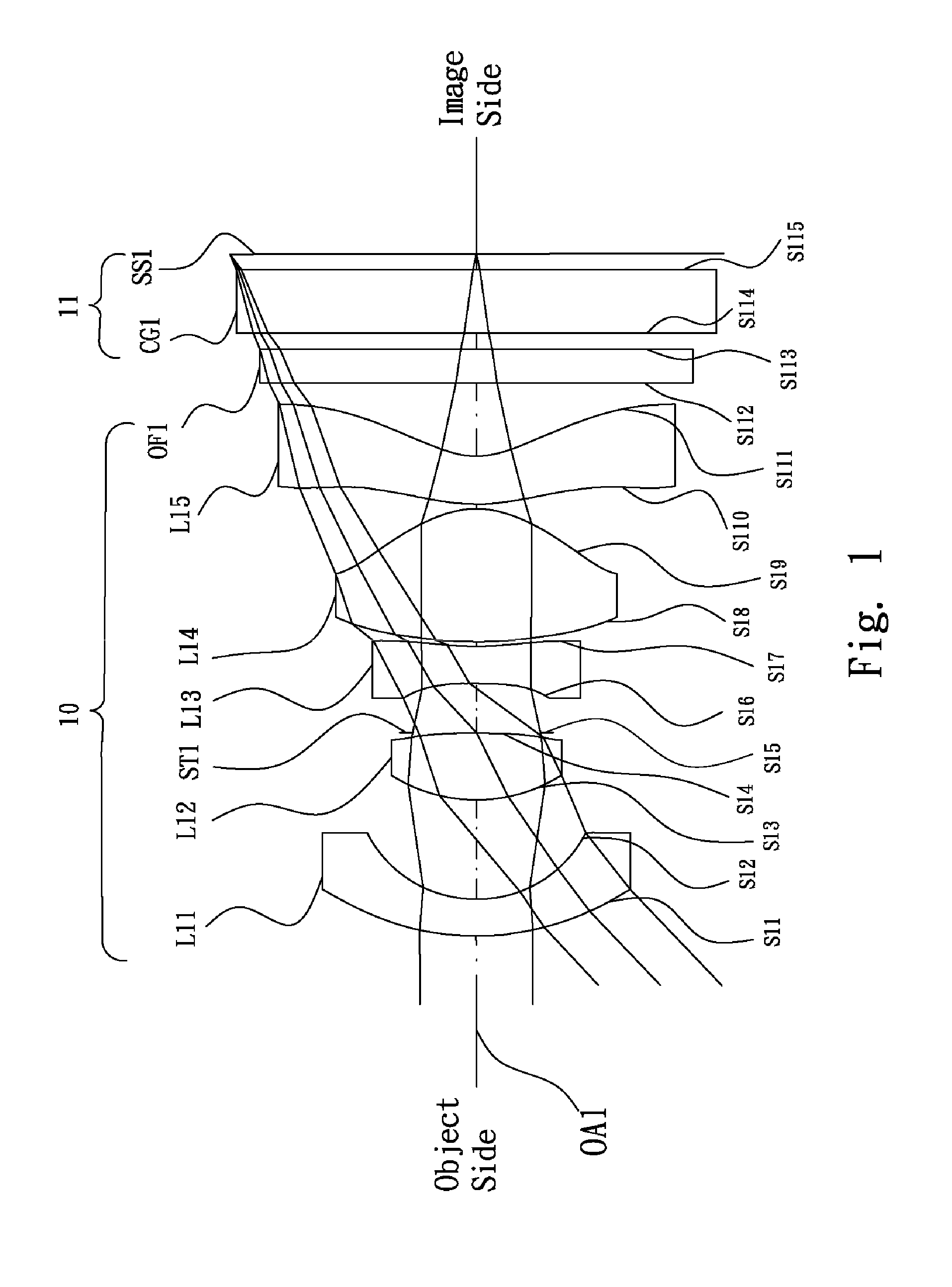
[0050]Referring to FIG. 1, FIG. 1 is a lens layout and optical path diagram of the slim lens assembly in accordance with the invention. The Slim lens assembly 10 includes a first lens L11, a second lens L12, a stop ST1, a third lens L13, a fourth lens L14, a fifth lens L15 and a optical filter OF1, all of which are arranged in sequence from an object side to an image side along an optical axis OA1. An image sensor 11 is disposed between the optical filter OF1 and the image side. A sensing surface SS1 of the image sensor 11 is disposed in the image plane. The first lens L11 is made of plastic material. The first lens L11 is a convex-concave lens with negative refractive power, the convex surface S11 of the first lens L11 faces the object side and the concave surface S12 of the first lens L11 faces the image side, wherein both of the convex surface S11 and concave surface S12 are aspheric surfaces. The second lens L12 is made of plastic material. The second lens L12 is a biconvex lens...

second embodiment

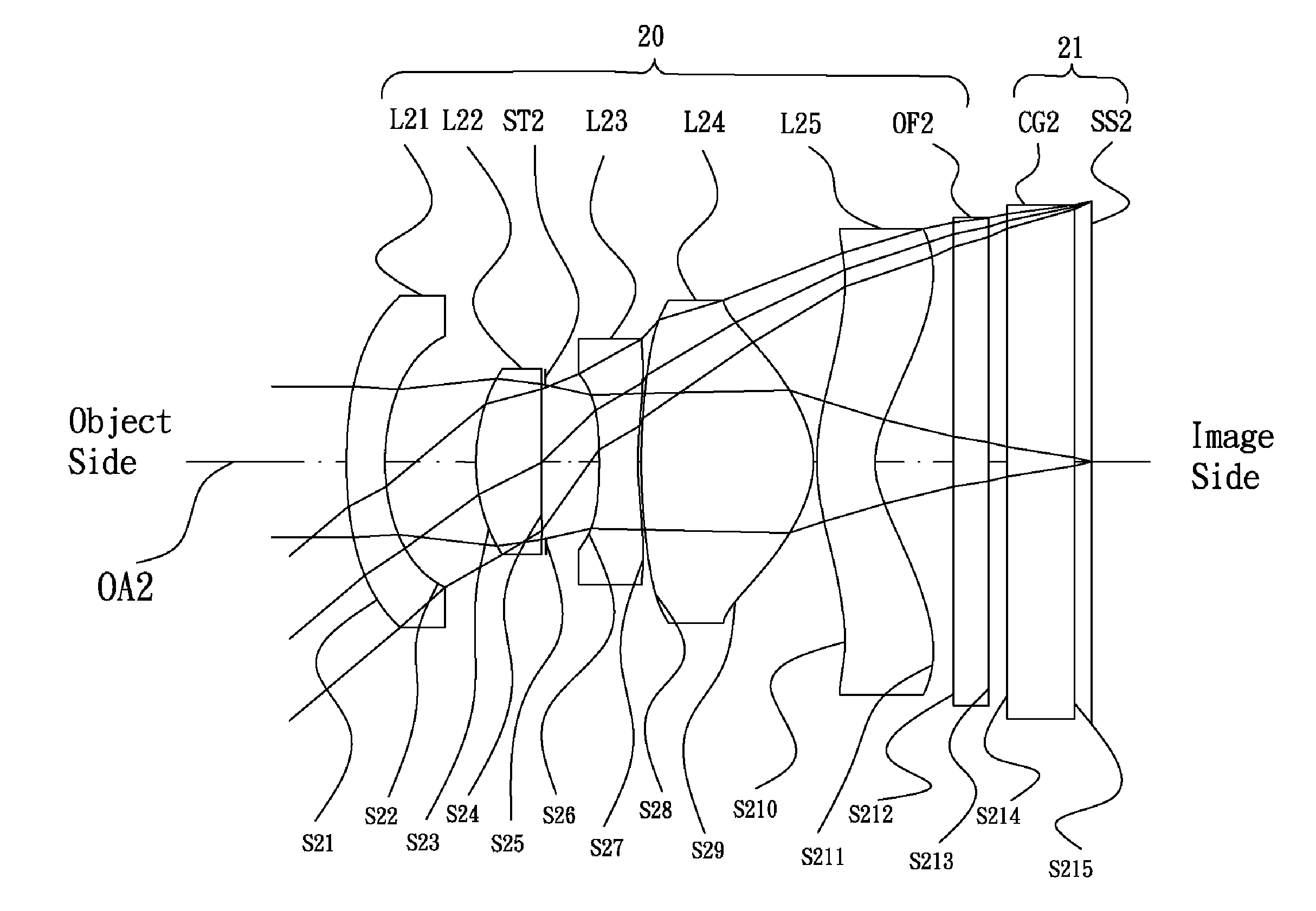
[0056]Referring to FIG. 3, FIG. 3 is a lens layout and optical path diagram of the slim lens assembly in accordance with the invention. The Slim lens assembly 20 includes a first lens L21, a second lens L22, a stop ST2, a third lens L23, a fourth lens L24, a fifth lens L25 and a optical filter OF2, all of which are arranged in sequence from an object side to an image side along an optical axis OA2. An image sensor 21 is disposed between the optical filter OF2 and the image side. A sensing surface SS2 of the image sensor 21 is disposed in the image plane. The first lens L21 is made of plastic material. The first lens L21 is a convex-concave lens with negative refractive power, the convex surface S21 of the first lens L21 faces the object side and the concave surface S22 of the first lens L21 faces the image side, wherein both of the convex surface S21 and concave surface S22 are aspheric surfaces. The second lens L22 is made of plastic material. The second lens L22 is a convex-concav...

third embodiment

[0062]Referring to FIG. 5, FIG. 5 is a lens layout and optical path diagram of the slim lens assembly in accordance with the invention. The Slim lens assembly 30 includes a first lens L31, a second lens L32, a stop ST3, a third lens L33, a fourth lens L34, a fifth lens L35 and a optical filter OF3, all of which are arranged in sequence from an object side to an image side along an optical axis OA3. An image sensor 31 is disposed between the optical filter OF3 and the image side. A sensing surface SS3 of the image sensor 31 is disposed in the image plane. The first lens L31 is made of plastic material. The first lens L31 is a convex-concave lens with negative refractive power, the convex surface S31 of the first lens L31 faces the object side and the concave surface S32 of the first lens L31 faces the image side, wherein both of the convex surface S31 and concave surface S32 are aspheric surfaces. The second lens L32 is made of plastic material. The second lens L32 is a convex-concav...


PUM


Abstract

A slim lens assembly includes a first lens, a second lens, a third lens, a fourth lens and a fifth lens, all of which are arranged in sequence from an object side to an image side along an optical axis. The first lens is a convex-concave lens with negative refractive power and includes a convex surface facing the object side and a concave surface facing the image side. The second lens is with positive refractive power. The third lens is a biconcave lens with negative refractive power. The fourth lens is a biconvex lens with positive refractive power. The fifth lens is a convex-concave lens with negative refractive power and includes a convex surface facing the object side and a concave surface facing the image side.

Description

BACKGROUND OF THE INVENTION[0001]1. Field of the Invention[0002]The invention relates to a slim lens assembly.[0003]2. Description of the Related Art[0004]In recent years, portable electronic products have been gradually developed toward miniaturization and lightweight for people to carry and use conveniently. The lens assemblies that are used for portable electronic products also require miniaturization and lightweight. In addition to miniaturization and lightweight, higher optical performance that can achieve high image quality is required. In conclusion, miniaturization, lightweight and high optical performance are essential elements to a lens assembly.[0005]In order to achieve the purposes of miniaturization, lightweight and high optical performance, aspheric plastic lens begins to be used in some lens assemblies. From the beginning of using one or two aspheric plastic lenses, to the present of only using aspheric plastic lens in some lens assemblies, the use of aspheric plastic...

Claims


Application Information

Patent Timeline
Patent Type & Authority Applications(United States)
IPC IPC(8): G02B3/04G02B3/00
CPCG02B3/00G02B3/04G02B13/0045G02B13/04G02B9/60G02B13/0015G02B13/18
Inventor SHIH, PO-YUAN
Owner SINTAI OPTICAL SHENZHEN CO LTD
Why Eureka
Try Eureka