Ankle-Foot Prosthesis for Automatic Adaptation to Sloped Walking Surfaces
What is AI technical title?
AI technical title is built by Patsnap AI team. It summarizes the technical point description of the patent document.
a technology of automatic adaptation and ankle foot, which is applied in the field of prosthetics and orthotics, can solve the problems of high cost of current available system, inability to meet the needs of the majority of users of lower limb prosthesis, and associated loss of energy
Active Publication Date: 2014-03-27
THE GOVERNMENT OF THE UNITED STATES OF AMERICA AS REPRESENTED BY THE DEPT OF VETERANS AFFAIRS +1
View PDF12 Cites 14 Cited by
Summary
Abstract
Description
Claims
Application Information
AI Technical Summary
This helps you quickly interpret patents by identifying the three key elements:
Problems solved by technology
Method used
Benefits of technology
Benefits of technology
The present invention is about an ankle-foot prosthesis that can make a person's gait more natural and comfortable. It is also more energy-efficient, simple in design, durable, and user-friendly. The prosthesis can automatically adapt to different sloped surfaces and can be used for walking, standing, and swaying tasks. It can also switch between a stable mode and a comfortable mode. Overall, the invention provides a better quality of life for people who have had their ankle or foot amputated.
Problems solved by technology
These systems can work nicely on level terrain but cause instabilities when lower limbprosthesis users walk on sloped surfaces.
The inherent problem with damping control of the ankle is the associated loss of energy that occurs.
However, this system requires multiple steps on a new terrain before it is able to adapt to the new slope.
The only currently available system on the market (iWalk BiOM) is expensive, making it impractical for the majority of lower limbprosthesis users.
Also, the high power requirements necessitate carrying additional batteries and frequent charging of batteries.
Method used
Image
Click on the blue label to locate the original text in one second.
Reading with bidirectional positioning of images and text.
Examples
Embodiment Construction
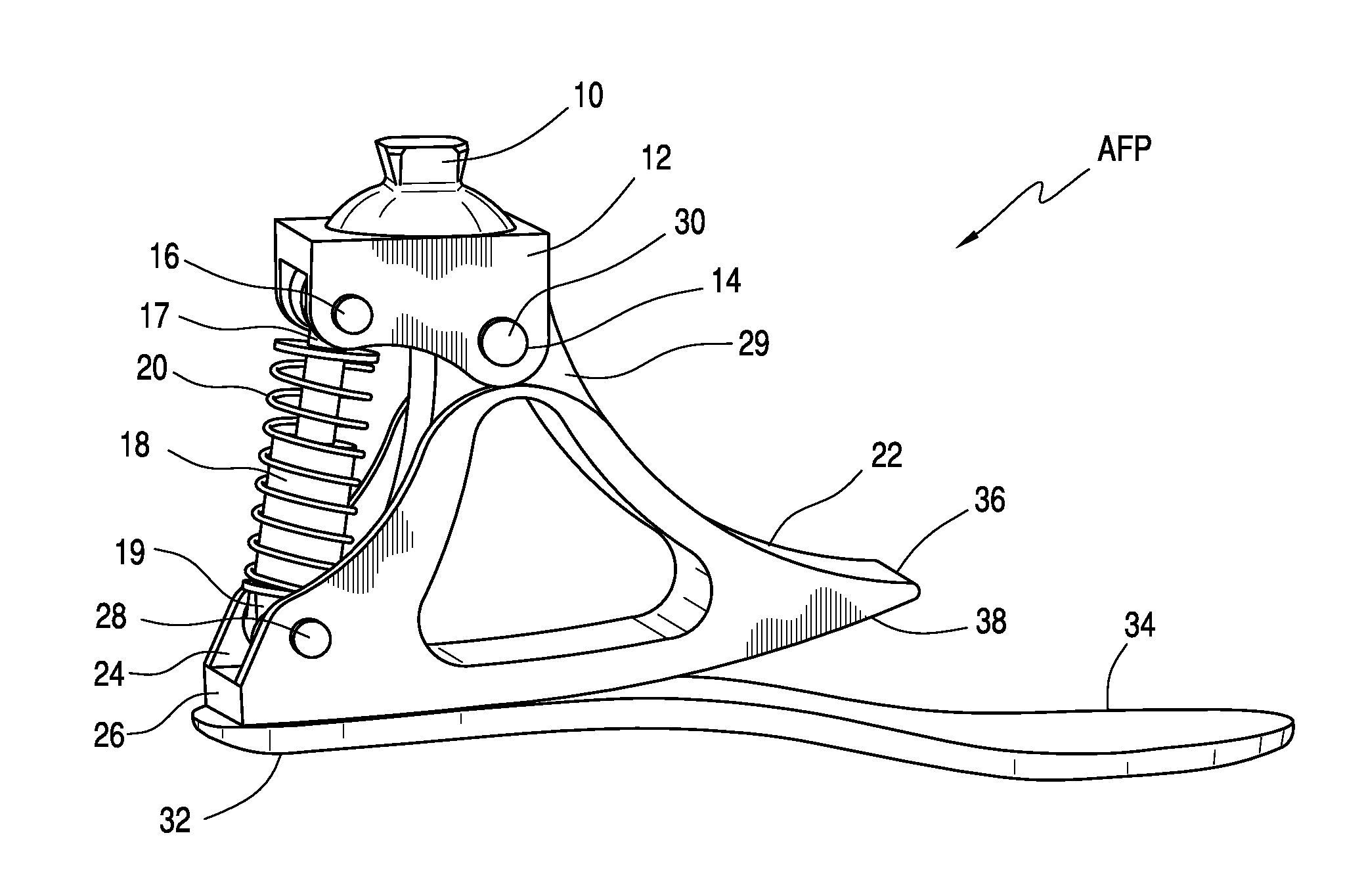
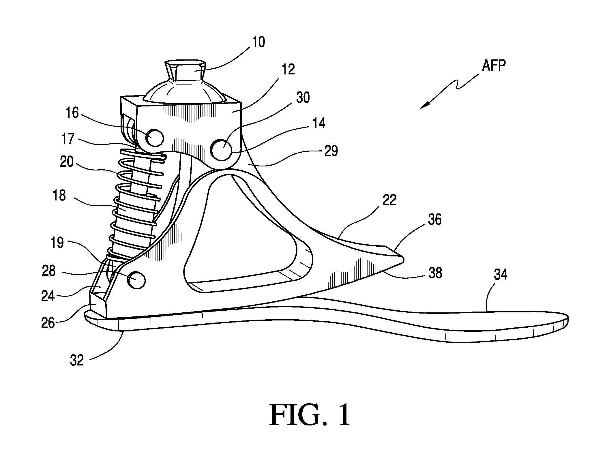
[0026]Referring to FIG. 1, a preferred embodiment of the ankle-foot prosthesis AFP will be described. As shown, a generally pyramid-like attachment part 10, consistent with standard endoskeletal componentry in prosthetics, is provided at the top of a yoke 12, on the opposite ends of which are holes drilled for front and rear pivotal attachments 14 and 16, respectively. The rear pivot 16 attaches to one end 17 of a preferably microprocessor controlled damper device 18 (to be described in more detail below). A neutralizing spring 20 is connected in parallel to the damper 18, such that its length change is equal to that of the damper.
[0027]The damper device 18 attaches on its other end 19 to an ankle frame 22, which has a yoke opening 24 and holes drilled at its posterior end 26 to pivotally attach to the damper 18 using a shaft 28. The “ankle” of the device AFP is a shaft 30 connecting the yoke 12 with the apex 29 of the ankle frame 22.
[0028]The ankle frame 22 attaches with one or mor...
PUM
Abstract
An ankle-foot prosthesis includes a foot plate, an ankle frame attached to the foot plate, a yoke pivotally connected to the ankle frame and including a member for attaching to a leg, a damper having a first end connected to the yoke and a second end connected to the ankle frame, and a control mechanism for switching the damper between low and high settings.
Description
CROSS-REFERENCE TO RELATED APPLICATIONS[0001]The present application claims priority based on prior two (2) U.S. Provisional Applications Ser. No. 61 / 703,799, filed Sep. 21, 2012, and Ser. No. 61 / 851,740, filed Mar. 13, 2013, both hereby incorporated herein in their entirety by reference. The present application is further related to International Application No. PCT / US2007 / 022208, filed Oct. 17, 2007 (WO 2008 / 048658, Apr. 24, 2008) (U.S. application Ser. No. 12 / 311,818, filed Apr. 13, 2009, Published as US 2010 / 0185301, on Jul. 22, 2010), U.S. application Ser. No. 12 / 462,056, filed Jul. 28, 2009 (Published as US 2010 / 0030343, on Feb. 4, 2010), U.S. application Ser. No. 13 / 066,361, filed Apr. 12, 2011 (Published as US 2012 / 0016493, on Jan. 19, 2012), U.S. application Ser. No. 13 / 374,881, filed Jan. 20, 2012 (Published as US 2013 / 0006386, on Jan. 3, 2013), and International Application No. PCT / US2011 / 000675, filed Apr. 4, 2011 (WO 2011 / 129892, Oct. 20, 2011), all of which are hereby ...
Claims
Application Information
Patent Timeline
Application Date:The date an application was filed.
Publication Date:The date a patent or application was officially published.
First Publication Date:The earliest publication date of a patent with the same application number.
Issue Date:Publication date of the patent grant document.
PCT Entry Date:The Entry date of PCT National Phase.
Estimated Expiry Date:The statutory expiry date of a patent right according to the Patent Law, and it is the longest term of protection that the patent right can achieve without the termination of the patent right due to other reasons(Term extension factor has been taken into account ).
Invalid Date:Actual expiry date is based on effective date or publication date of legal transaction data of invalid patent.
Patent Type & AuthorityApplications(United States)

