
Wire reel, reinforcing bar binding machine, and rotational information detecting method

a technology of reinforcing bar and wire reel, which is applied in the direction of instruments, measurement devices, transportation and packaging, etc., can solve the problems of easy erroneous detection, restricted shape of wire reel, and easy erroneous detection, so as to prevent erroneous detection

Active Publication Date: 2014-04-03
MAX CO LTD
View PDF3 Cites 17 Cited by
  • Summary
  • Abstract
  • Description
  • Claims
  • Application Information

AI Technical Summary

Benefits of technology

[0011]Additionally, a second object of the invention is to provide a wire reel for a reinforcing bar binding machine capable of eliminating erroneous detection based on a height difference or the like, capable of receiving sufficient light by a light-receiving element even if the transmission of light is small, and capable of improving the resolution of a sensor.
[0033]In the above configuration, inner tube is coaxially formed inside the hub portion, the side wall is formed between the hub portion and the inner tube, a gap is provided between the light-transmitting portions and the outside surface of the inner tube to such an extent that the light from the light-emitting element is prevented from being reflected by the outside surface of the inner tube and being transmitted through the light-transmitting portions. Therefore, even if the light from the light-emitting element is reflected by the outside surface of the inner tube, the light hardly enter the light-transmitting portions, and erroneous detection can be prevented effectively.

Problems solved by technology

However, there are the following problems in the detection by the reflective photosensor.
Accordingly, as shown by a line 70 in FIG. 28, erroneous detection occurs since output signals by the photosensor change and a voltage is not returned, and erroneous detection easily occurs even by attachment of sand or dust.
For this reason, the shape of the wire reel is also largely restricted, and it is difficult to increase resolution.
Additionally, since the number of white projections is also restricted, various kinds of information cannot be given.
This error becomes the detection error of feed amount of about 50 mm even at the last stage of rotation of the wire reel where an exact wire feed amount can be detected.
Accordingly, by the existing sensor, precise detection of rotation of the wire reel at the time of wire feed cannot be performed, and a decrease in wire feed amount caused by wear of the feed gears cannot be detected.

Method used


Image

  • Wire reel, reinforcing bar binding machine, and rotational information detecting method
  • Wire reel, reinforcing bar binding machine, and rotational information detecting method
  • Wire reel, reinforcing bar binding machine, and rotational information detecting method

Examples


Embodiment Construction

[0087]An exemplary embodiment of the invention is described in reference with drawings.

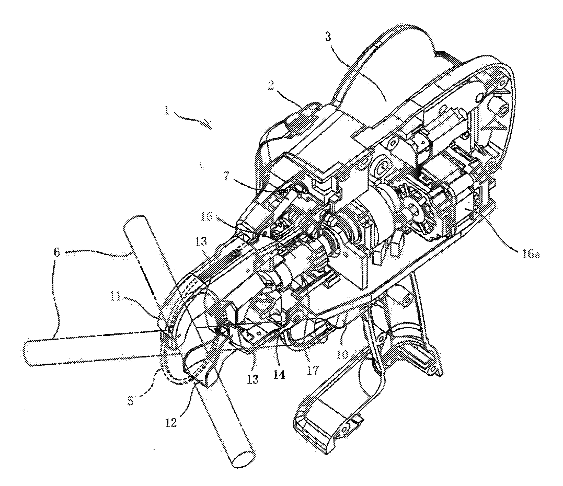
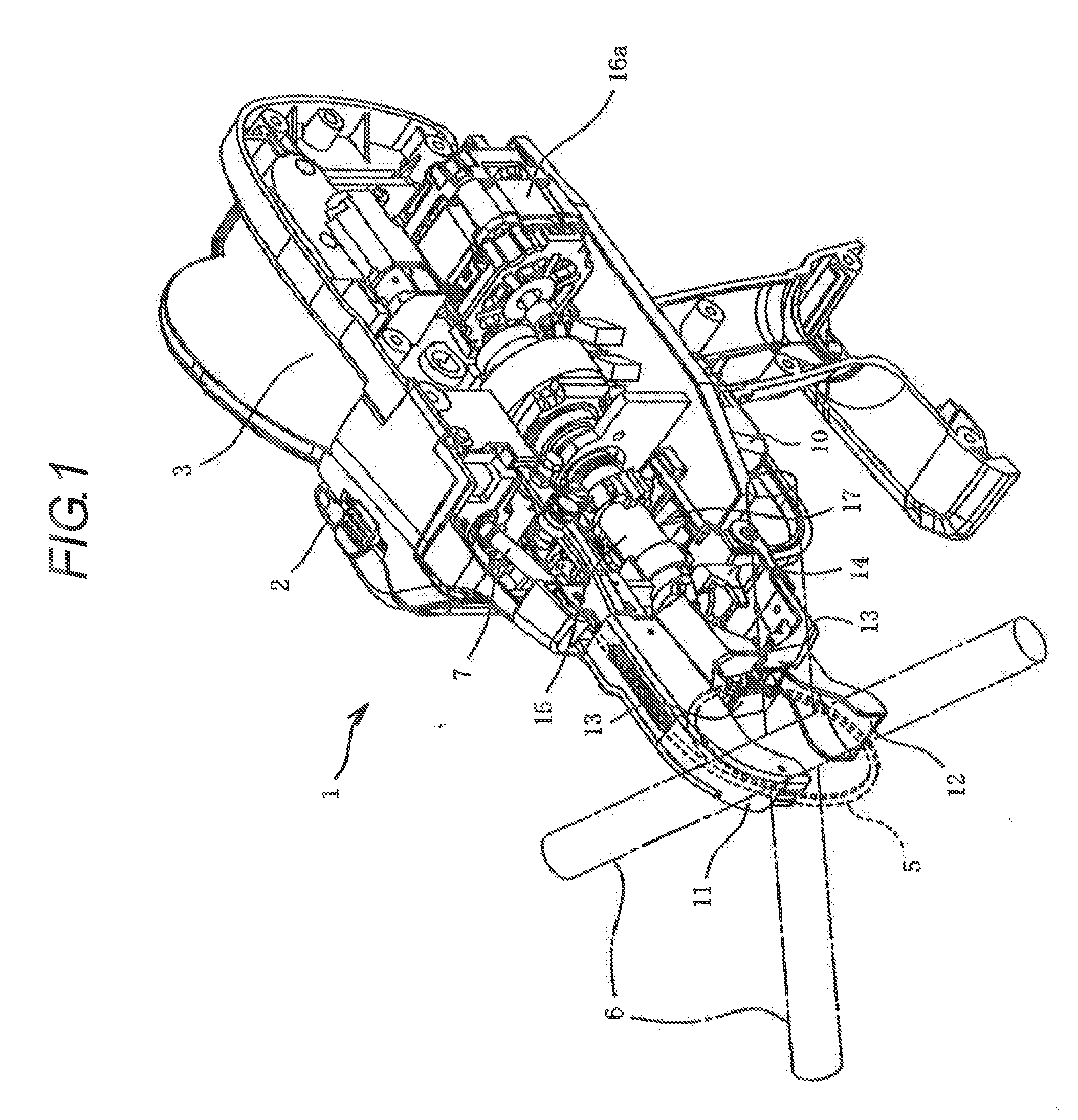
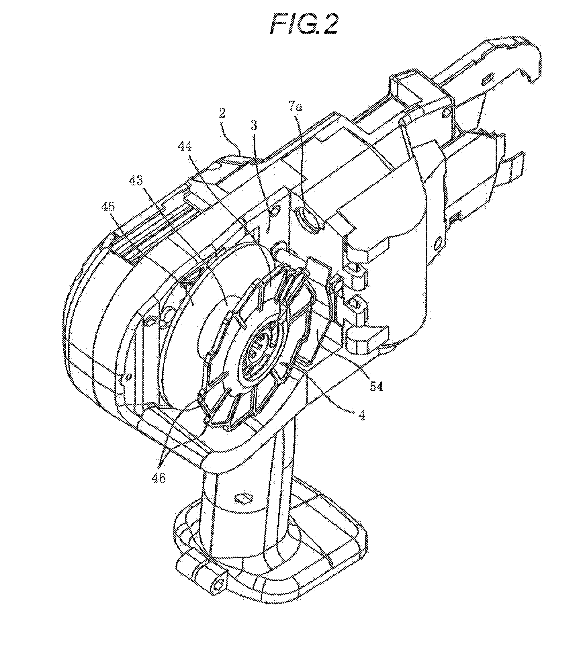
[0088]In FIGS. 1 to 4, reference numeral 1 represents a reinforcing bar binding machine. The reinforcing bar binding machine 1 mounts a wire reel 4 around which a wire 5 for binding of a reinforcing bar is wound on a housing chamber 3 provided in a binding machine body 2, delivers the wire 5 while rotating the wire 5, and winds and then twists the wire 5 around a reinforcing bar 6, thereby binding the reinforcing bar 6.

[0089]The binding machine body 2 is provided with a guide pipe 7 which allows the wire 5 pulled out from the wire reel 4 to pass therethrough. One end 7a of the guide pipe 7 is opened to the housing chamber 3, and the other end thereof is located in front of a guide portion 11 which will be described later. A pair of feed gears 8 as a feeding means of the wire 5 is disposed in an intermediate portion of the guide pipe 7. The wire 5 is sandwiched by feed rollers formed integrally wit...


PUM

PropertyMeasurementUnit
widthaaaaaaaaaa
widthaaaaaaaaaa
diameteraaaaaaaaaa

Abstract

A wire reel is detachably provided in a housing chamber of a binding machine body which binds a reinforcing bar. The wire reel includes a cylindrical hub portion which winds a wire, and a pair of parallel flanges overhanging outward from both external peripheral ends of the hub portions. A side wall inside the hub portion is formed of light-transmitting portions which allow the light from a transmissive photosensor provided in the binding machine body to be transmitted therethrough.

Description

BACKGROUND OF THE INVENTION[0001]1. Field of the Invention[0002]The present invention relates to a reinforcing bar binding machine which feeds a wire of a wire reel, winds the wire around a reinforcing bar in a loop shape, and then twists and binds the wire, a wire reel attached to a reinforcing bar binding machine body and having information display means of the type or the like of a wire reel, and a rotational information detecting method which detects the rotational information from an information detection region of the wire reel.[0003]2. Background Art[0004]In a conventional reinforcing bar binding machine, a wire reel around which a wire is wound is held at a rear portion of the binding machine, the wire is pulled out by feed gears of a wire feeding device from the wire reel and delivered forward when a switch is turned on and a trigger is operated, the wire is supplied in a loop shape from a curved portion of the tip of a guide arm and wound around a reinforcing bar, and then...

Claims


Application Information

Patent Timeline
Patent Type & Authority Applications(United States)
IPC IPC(8): B65H75/14
CPCB65H75/14B65H49/18B65H51/30B65H2701/52E04G21/123G01D5/3473B21F15/04B65H2701/362
Inventor NAKAGAWA, YASUSHIKATOU, KOUJIKOBAYASHI, TSUYOSHIYAMAMOTO, YU
Owner MAX CO LTD
Learn More