Chuck table

Active Publication Date: 2014-04-03
DISCO CORP
View PDF23 Cites 7 Cited by
  • Summary
  • Abstract
  • Description
  • Claims
  • Application Information

AI Technical Summary

Benefits of technology

[0008]With this configuration, the peripheral portion of the workpiece comes into contact with the annular seal member formed from an elastic member, so that a reduction in air-tightness due to the warp can be prevented to thereby properly hold the workpiece under suction. Further, the annular seal member is deformed by the vacuum in holding the workpiec

Problems solved by technology

In this case, the chuck table cannot exert a sufficient suction

Method used


Image

  • Chuck table
  • Chuck table
  • Chuck table

Examples


Example

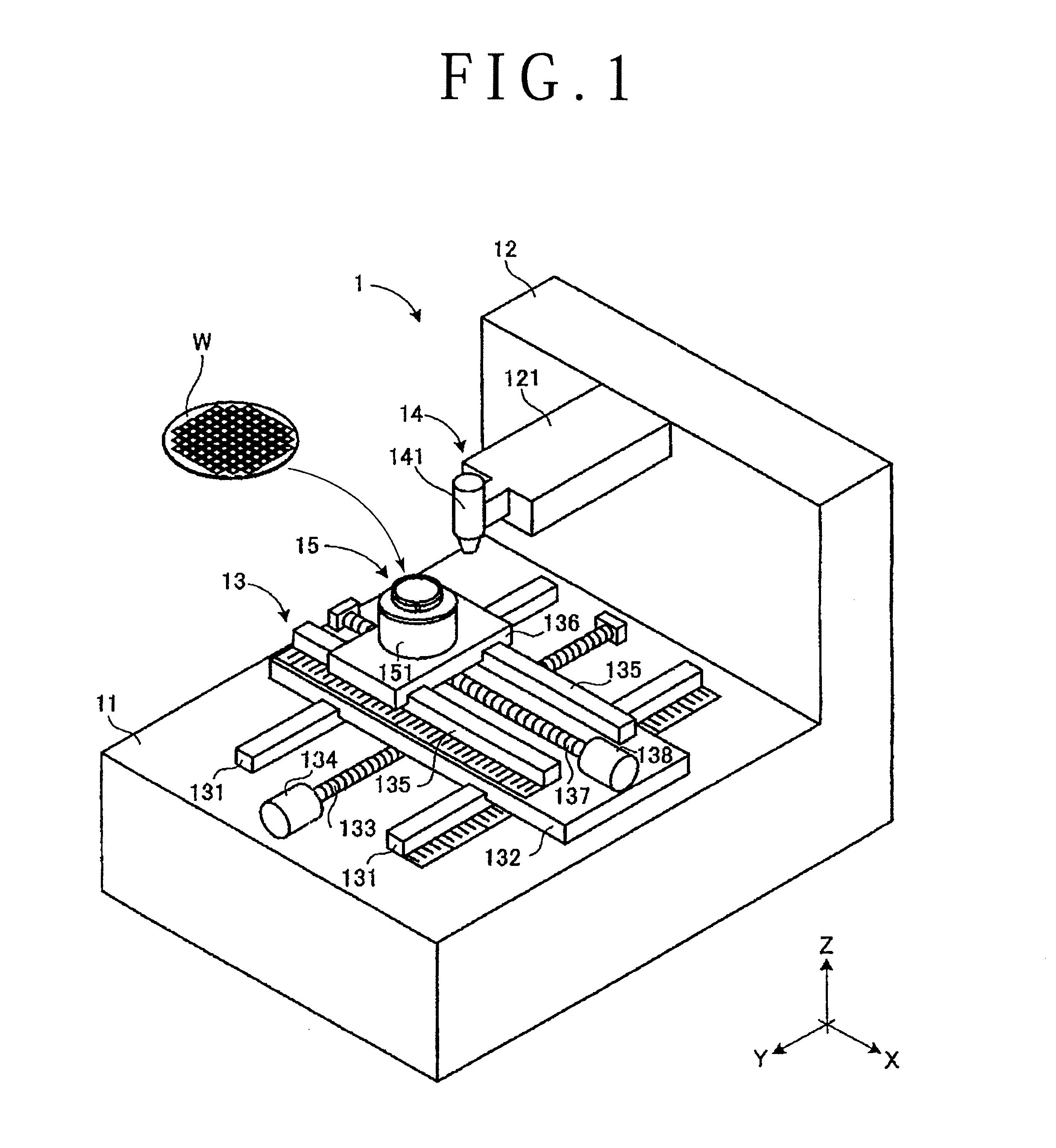
[0013]A preferred embodiment of the present invention will now be described with reference to the attached drawings. FIG. 1 is a perspective view of a laser processing apparatus (processing apparatus) 1 including a chuck table 15 according to this preferred embodiment. A wafer (workpiece) W is also shown in FIG. 1 in relation with the laser processing apparatus 1. The laser processing apparatus 1 is so configured as to apply a laser beam to the wafer W held on the chuck table 15, thereby allowing laser processing of the wafer W.

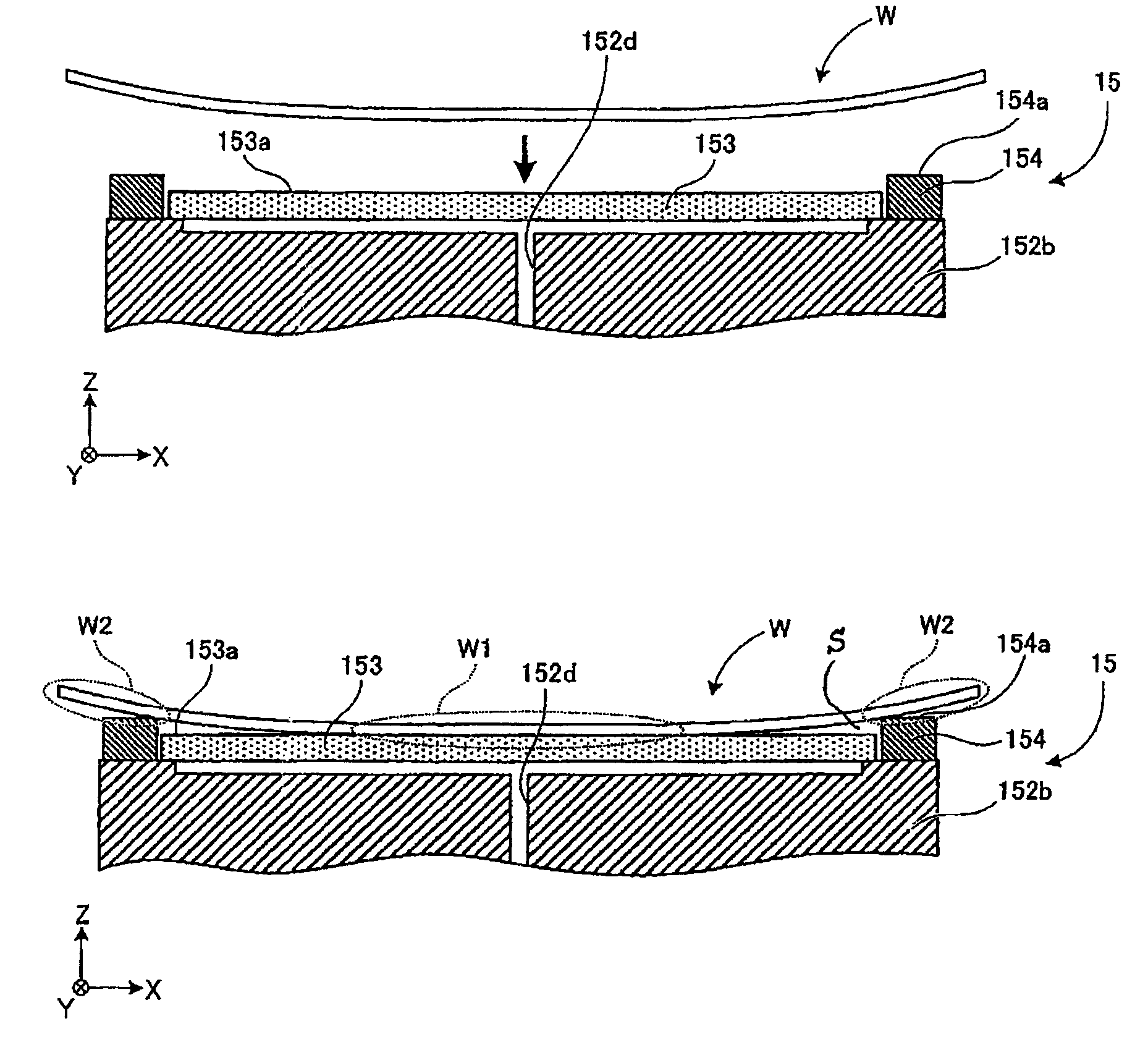
[0014]As shown in FIG. 1, the wafer W is a disk-shaped member. The front side (upper surface) of the wafer W is partitioned into a plurality of regions by a plurality of crossing streets. A plurality of devices are respectively formed in these regions partitioned by the streets on the front side of the wafer W. Preferably, a protective tape (not shown) is attached to the back side or front side of the wafer W coming into contact with the chuck table 15 in hol...


PUM

PropertyMeasurementUnit
Circumferenceaaaaaaaaaa

Abstract

A chuck table holds a workpiece having a warp. The chuck table includes a suction holding member having a suction holding surface for holding the workpiece under suction, and an annular seal member provided around the outer circumference of the suction holding member for supporting a peripheral portion of the workpiece. The annular seal member is formed from an elastic member. The upper surface of the annular seal member is set higher in level than the suction holding surface according to the warp of the workpiece. In holding the workpiece on the chuck table under suction, vacuum leaking from the gap between the workpiece and the suction holding surface due to the warp of the workpiece is applied to the space defined by the workpiece and the annular seal member, thereby elastically deforming the annular seal member to flatten the upper surface of the workpiece.

Description

BACKGROUND OF THE INVENTION[0001]1. Field of the Invention[0002]The present invention relates to a chuck table for holding a workpiece such as a wafer.[0003]2. Description of the Related Art[0004]A workpiece such as a wafer having devices formed on the front side is processed by a laser processing apparatus including a laser processing unit, for example. This laser processing apparatus includes a chuck table for holding the workpiece in processing the workpiece. The chuck table has a suction holding member formed of a porous ceramic material. Accordingly, the workpiece is held under suction on the suction holding member of the chuck table. By relatively moving the chuck table holding the workpiece thereon with respect to the laser processing unit, the position of application of a laser beam to the workpiece is changed to allow the processing of the workpiece.SUMMARY OF THE INVENTION[0005]In some cases, the workpiece to be processed by the laser processing apparatus has a warp to a c...

Claims


Application Information

Patent Timeline
IPC IPC(8): B23B31/30
CPCB23B31/307B23K26/0006B23K37/0408B23K26/702B23K2103/56H01L21/6838H01L21/67288Y10T279/11B23K26/10
Inventor IIZUKA, KENTAROTERAJIMA, MASATO
Owner DISCO CORP
Why Eureka
Try Eureka