Apparatus for controlling the operation of an led, and method for controlling drive current thereof

a technology of led array and drive current, which is applied in the direction of electroluminescent light sources, electric lighting sources, and use of semiconductors. it can solve the problems of reducing the life of the led device, and achieve the effects of reducing the flicker phenomenon, preventing the rise in the temperature of the led array and the temperature of the led driving control circuit, and improving the power factor

Active Publication Date: 2014-04-10
KOREA ELECTROTECH RES INST
View PDF6 Cites 4 Cited by
  • Summary
  • Abstract
  • Description
  • Claims
  • Application Information

AI Technical Summary

Benefits of technology

[0018]In accordance with the present invention, the driving current of the LED array can be output in a sine wave form through the constant current control or constant power control even when input voltage fluctuates, thereby achieving advantages of suppressing harmonics, improving a power factor, minimizing a flicker phenomenon, and preventing a rise in temperature of the LED array and temperature of the LED driving control circuit.
[0019]Furthermore, the present invention is advantageous in that the circuit configuration of the apparatus for controlling the operation of LEDs can be simplified and the costs required to construct the corresponding circuit can be reduced due to the simplified circuit configuration.

Problems solved by technology

Furthermore, the conventional circuit 1 for operating an AC LED module using only the resistor 40 is problematic in that a flicker phenomenon, that is, a phenomenon in which light flickers, may be generated because the operation of a constant current for securing the lifespan and optical characteristics of an LED device is very limited, and in that the lifespan of an LED device is reduced because the operation voltage of the LED device that varies depending on temperature and the forward loss voltage of the LED device cannot be maintained.

Method used


Image

  • Apparatus for controlling the operation of an led, and method for controlling drive current thereof
  • Apparatus for controlling the operation of an led, and method for controlling drive current thereof
  • Apparatus for controlling the operation of an led, and method for controlling drive current thereof

Examples


first embodiment

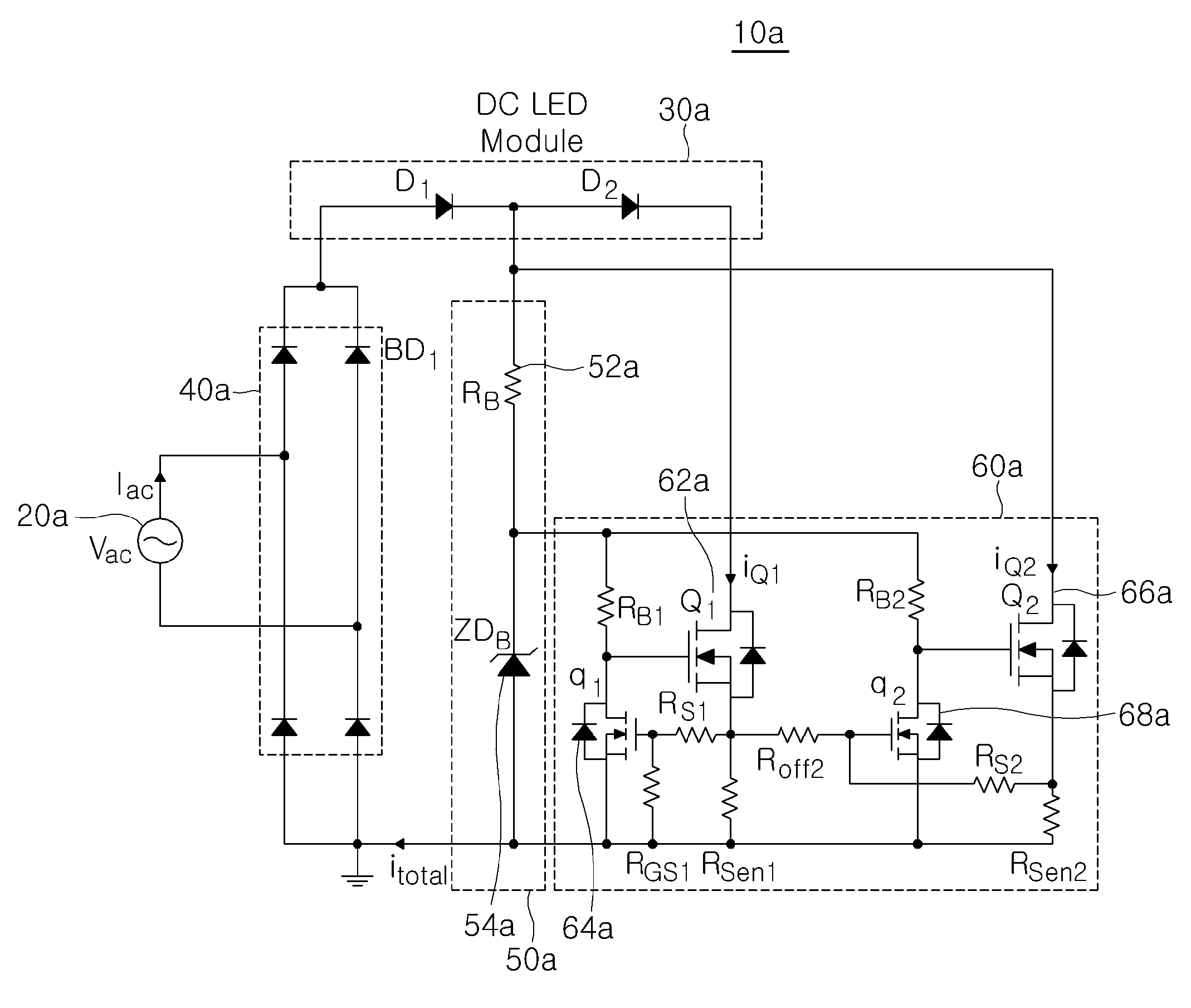
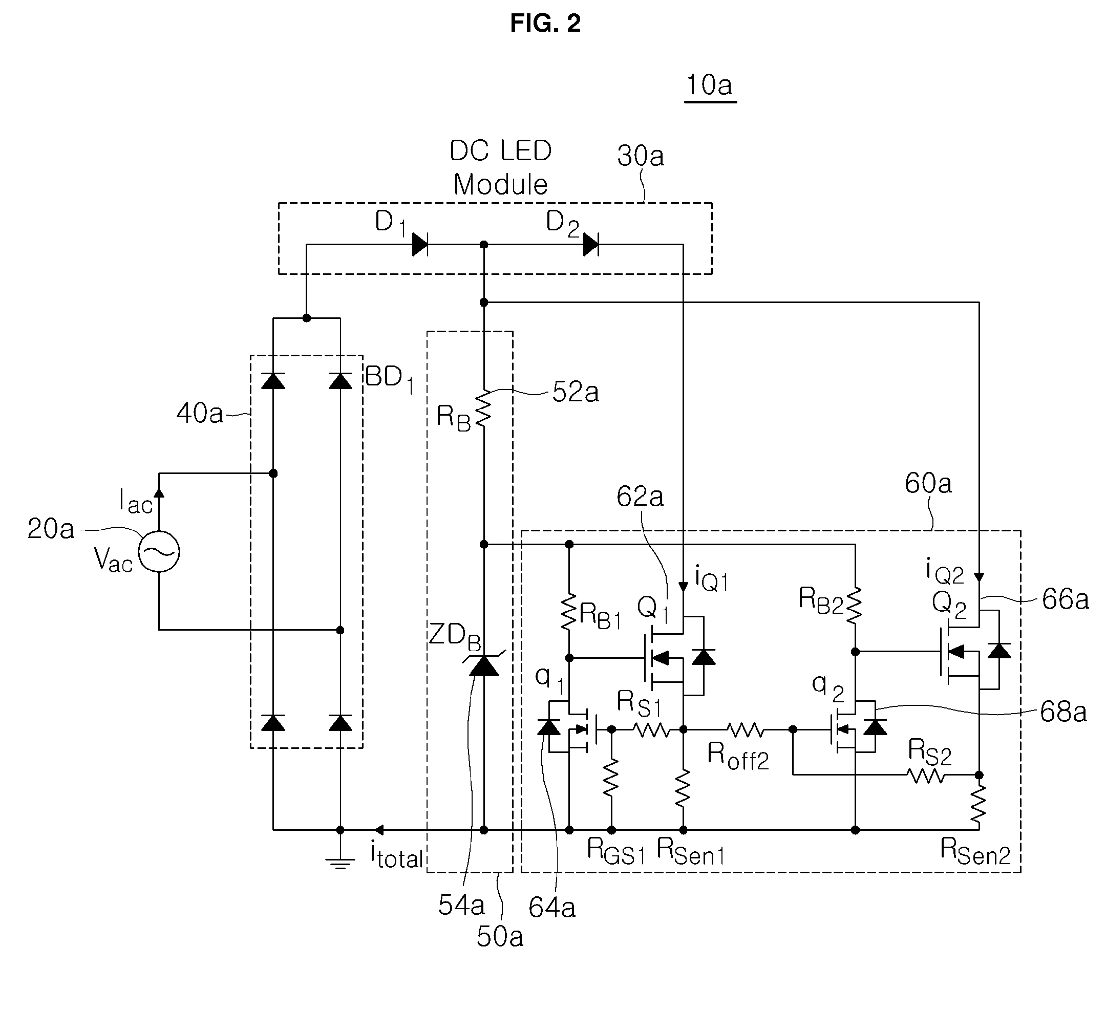
[0040]FIG. 2 is a circuit diagram of an apparatus for controlling the operation of LEDs according to the present invention.

[0041]As shown in FIG. 2, the apparatus 10a for controlling the operation of LEDs according to the first embodiment of the present invention includes an AC power source 20a, an LED array 30a, a rectification unit 40a, an operation control voltage generation unit 50a, and an operating current control unit 60a.

[0042]The AC power source 20a supplies power for the operation of the LED array 30a, and the input side of the LED array 30a is connected to the output side of the AC power source 20a.

[0043]The LED array 30a includes a plurality of LEDs that are connected in series. Each of the LEDs may be a DC-operated LED that is operated by DC power.

[0044]The rectification unit 40a is connected between the output side of the AC power source 20a and the input side of the LED array 30a. In greater detail, the output side of the rectification unit 40a is connected to the i...

second embodiment

[0064]FIG. 3 is a circuit diagram of an apparatus for controlling the operation of LEDs according to the present invention.

[0065]As shown in FIG. 3, the apparatus for controlling the operation of LEDs 10b according to the second embodiment of the present invention includes an AC power source 20b, an LED array 30b, a rectification unit 40b, an operation control voltage generation unit 50b, and an operating current control unit 60b.

[0066]The AC power source 20b supplies power for the operation of the LED array 30b, and the input side of the LED array 30b is connected to the output side of the AC power source 20b.

[0067]The LED array 30b includes a plurality of LED pairs 32b and 34b that are connected in parallel in a backward direction. Each of the LEDs of the LED pairs 32b and 34b may be an AC-operated LED that is operated by AC power.

[0068]The rectification unit 40b is connected between the input side of the AC power source 20b and the input side of the LED array 30b and between th...

third embodiment

[0094]FIG. 5 is a circuit diagram of an apparatus for controlling the operation of LEDs according to the present invention.

[0095]As shown in FIG. 5, the apparatus 10a for controlling the operation of LEDs according to the third embodiment of the present invention includes an AC power source 20a, an LED array 30a, a rectification unit 40a, an operation control voltage generation unit 50a, and an operating current control unit 60a.

[0096]The AC power source 20a supplies power for the operation of the LED array 30a, and the input side of the LED array 30a is connected to the output side of the AC power source 20a.

[0097]The LED array 30a includes a plurality of LEDs connected in series, and each of the LEDs may be a DC-operated LED that is operated by DC power.

[0098]The rectification unit 40a is connected between the output side of the AC power source 20a and the input side of the LED array 30a. In greater detail, the output side of the rectification unit 40a is connected to the input ...


PUM


Abstract

The present invention relates to an apparatus for controlling the operation of an LED and to a method for controlling the drive current thereof. More particularly, the present invention relates to an apparatus for controlling the operation of an LED, which is capable of driving a direct current-operated LED module or an alternating current-operated LED module using alternating current power, and to a method for controlling the drive current of the apparatus. According to the present invention, the drive current of an LED array can be output in the form of a sine wave by a constant-current regulation or constant-power regulation even when input voltage varies, thus suppressing harmonics, improving the power factor, minimizing flicker, and preventing a temperature increase in the LED array and in an LED operation control circuit.

Description

REFERENCE TO RELATED APPLICATIONS[0001]This is a continuation of pending International Patent Application PCT / KR2012 / 004109 filed on May 24, 2012, which designates the United States and claims priority of Korean Patent Application No. 10-2011-0049885 filed on May 26, 2011, Korean Patent Application No. 10-2011-0113848 filed on Nov. 3, 2011, and Korean Patent Application No. 10-2011-0113891 filed on Nov. 3, 2011, the entire contents of which are incorporated herein by reference.FIELD OF THE INVENTION[0002]The present invention relates generally to an apparatus for controlling the operation of light-emitting diodes (LEDs) and a method of controlling the driving current thereof and, more particularly, to an apparatus for controlling the operation of LEDs and a method of controlling the driving current thereof, which are capable of operating a direct current (DC)-operated LED module or an alternating current (AC)-operated LED module using an AC power source.BACKGROUND OF THE INVENTION[0...

Claims


Application Information

Patent Timeline
Patent Type & Authority Applications(United States)
IPC IPC(8): H05B33/08H05B44/00
CPCH05B33/0824H05B37/02H05B33/0845H05B33/0809H05B45/395H05B45/44Y02B20/30H05B47/10
Inventor KIM, JONG HYUNRYU, MYUNG HYOBAEK, JU WONSEO, KILL SOOKIM, HYOUNG WOO
Owner KOREA ELECTROTECH RES INST
Why Eureka
Try Eureka