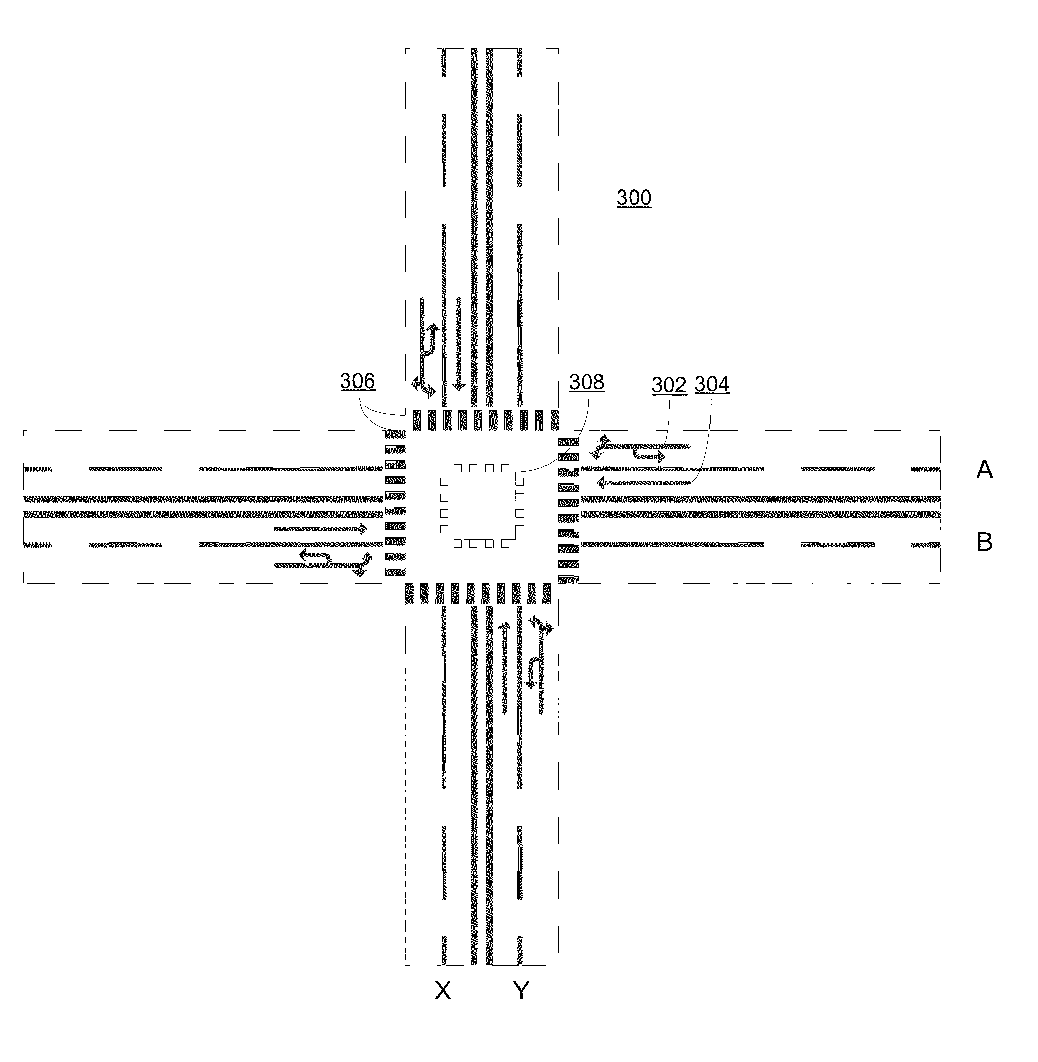
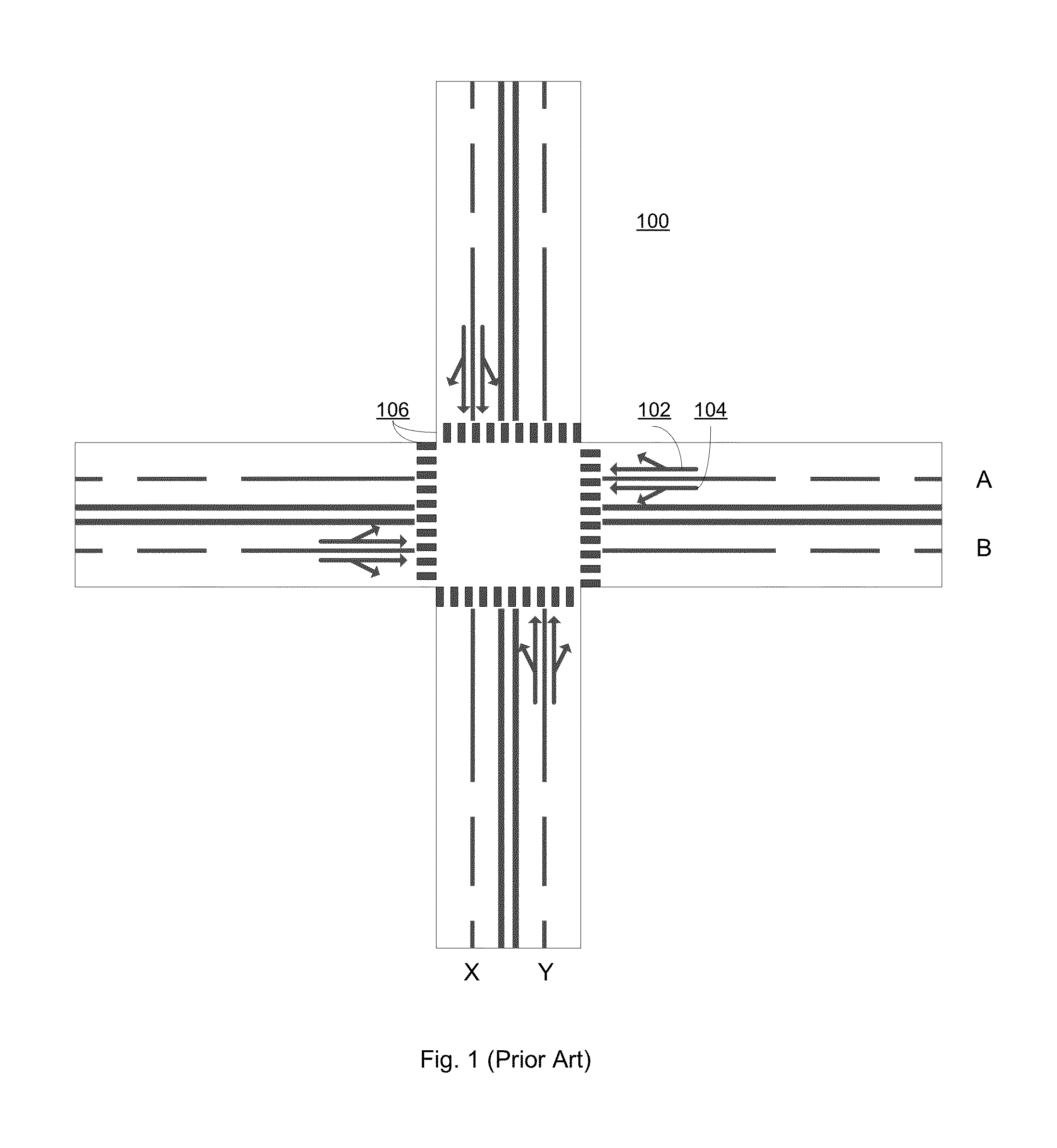
In some jurisdictions, vehicles on Road B, X and Y are allowed to turn right even under the
red light, further increasing the risk of collision between vehicles and pedestrians.
In some jurisdictions, vehicles on Road A, X and Y are allowed to turn right even under the
red light, further increasing the risk of collision between vehicle and
pedestrian.
In some jurisdictions, vehicles on Road A, B and Y are allowed to turn right even under the
red light, further increasing the risk of collision between vehicle and
pedestrian.
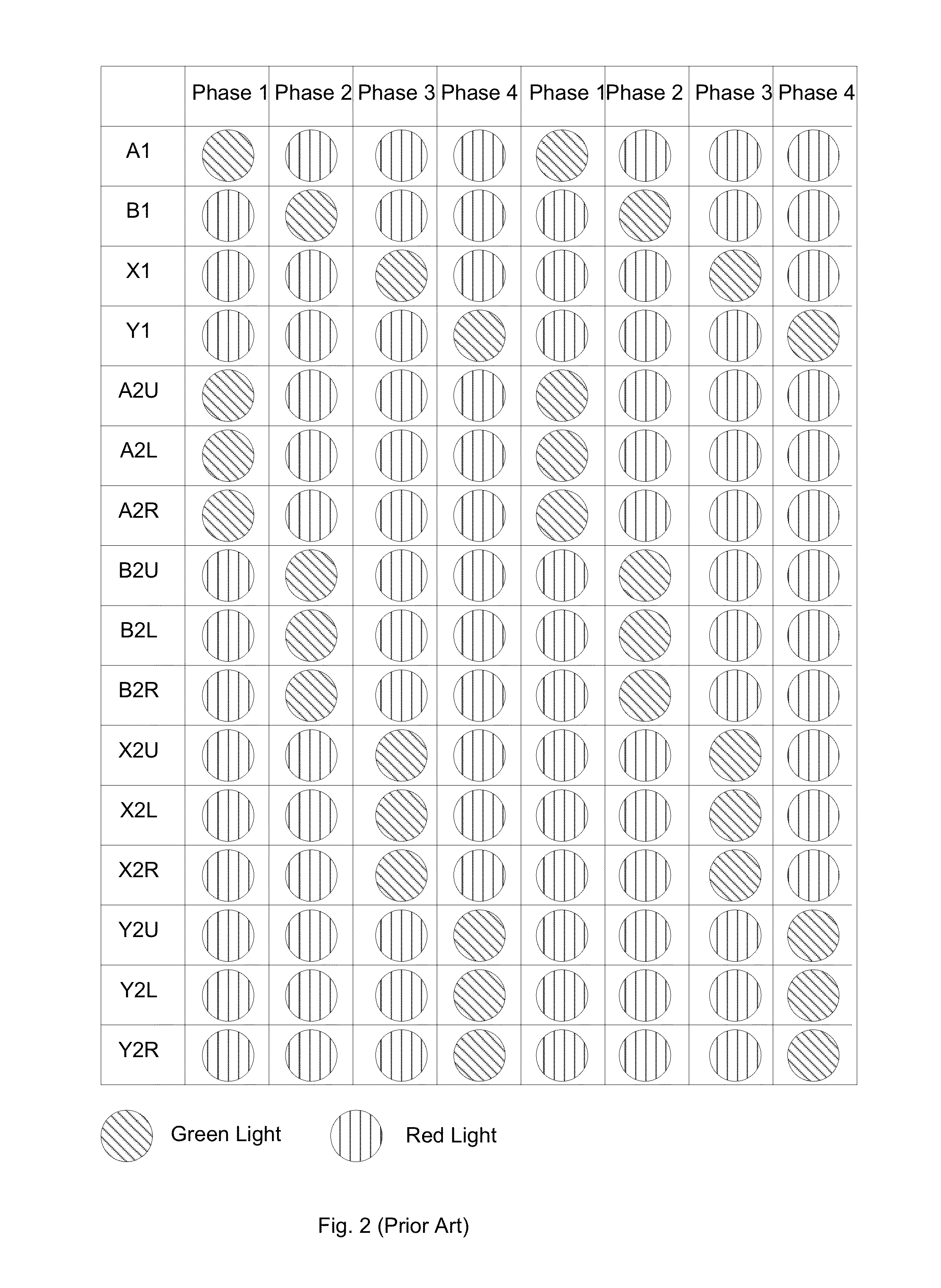
Therefore, there are conflicts in all of the four phases of traffic movements.
Therefore, as described in the preceding paragraphs, the traditional
traffic allocation system is both unsafe and inefficient enough.
Because pedestrians cross the road while vehicle traffics, including turn traffics, proceed, it is likely that
pedestrian and vehicle traffic could enter the same space at the same time to cause collision.
Lower speed in passing the intersection reduces the efficiency of the whole
traffic system.
In addition, U turn in the system is sometimes not allowed because it would significantly increase the risk of
traffic accident.
The present system of “Red / Green / Yellow”
signal combination is not a perfect traffic control method as it may result in many accidents, especially during the
signal change interval from yellow and following all-red periods.
Inevitably, when the signal of yellow light is starting, vehicle drivers often have a special difficulty, particularly at intersections of arterial roads where
speed limit may be as high as 50 mph.
Drivers may experience uncertainty to make a proper decision: while to continue proceeding may result a red-light running, yet at the same time it is also difficult to stop properly because an abrupt stop may cause rear-end crashes.
However, since the dilemma zone problem has two main safety issues of both red-light running and rear-end collisions, then neither Permissive yellow rule nor Restrictive yellow rule could satisfactorily solve the dilemma zone problem.
In real life, the mitigation effect of a prolonged yellow interval is very limited because a prolonged yellow interval often has been seemed as the extension of
green light signal by many drivers.
Similarly, possibility of speeding at the last second of yellow interval increases if drivers have learned that there is a prolonged all red period.
If an extended yellow light time cannot stop vehicles from entering the dilemma zone, then these new coming vehicles will still be involved the problem of dilemma zone, especially if these vehicles are still moving at high speed.
In the United States, this treatment had been experimented by several states but the performance was not satisfying.
Statistics suggest that drivers are more likely to speed up when a
green light flashes hence the possibility of crashes is actually increasing.
If arterial & major roads are not effectively organized and efficiently operated, the performance of both freeway network and collector /
distributor roads will be affected negatively and the whole
ground transportation network may suffer speed and
traffic capacity loss.
However, at present, at rush hours the LOS of an arterial road may often fall rapidly and the
operating speed may be below 30 km / h or even below 20 km / h, which means an arterial road has failed to meet its positioning.
At present, although a lane control light system may be adopted at some arterial roads, generally the performance is not satisfying.
The missing of a downward red arrow in a lane control light system is a serious deficiency.
The same problem also occurs at freeways, tunnels, and bridges.
If a number of vehicles arrived at the intersection during the red light interval, vehicles often have difficulty making a lane change after the red light interval, although the
green light signal is already on.
This is because that it is difficult to find a space to make a lane change since there are continuous vehicles moving at the neighbor lanes.
The lane change becomes increasingly difficult with increasing number of more lanes.
Traffic weavings may also significantly increase the risk of collisions.
Thus, if an arterial road is organized and signalized as an ordinary collector /
distributor road, the risk to road safety may be increased and the
traffic capacity may be lost.
The problem may be particularly pronounced during
rush hour, when a large numbers of vehicles arrive at the intersection.
The similar problem may also occur at a controlled / signalized crosswalk.
At signalized intersection, when a green light is on, it often takes substantial “
response time” for vehicles to reach a relatively high speed, starting to accelerate from unmoving status.
In some jurisdictions, vehicles and bicycles on Road B are allowed to turn right even under the red light, further increasing the risk of collision between vehicles and pedestrians.
The cyclist on road X is not allowed to make a left turn as such a turn would interfere with the traffic 2004.
In some jurisdictions, vehicles and bicycles on Road B are allowed to turn right even under the red light, further increasing the risk of collision between vehicles and pedestrians.
In some jurisdictions, vehicles and bicycles on road Y are allowed to turn right even under the red light, further increasing the risk of collision between vehicles and pedestrians.


