

Electronic device, accessory and method of operating electronic device and accessory
a technology of electronic devices and accessories, applied in the direction of instruments, computing, electrical apparatus casings/cabinets/drawers, etc., can solve the problem that the additional manufacturing cost must be spent on and achieve the effect of saving the cost of the circuit configuration of the accessory
- Summary
- Abstract
- Description
- Claims
- Application Information
AI Technical Summary
Benefits of technology
Problems solved by technology
Method used
Image

Examples
first embodiment
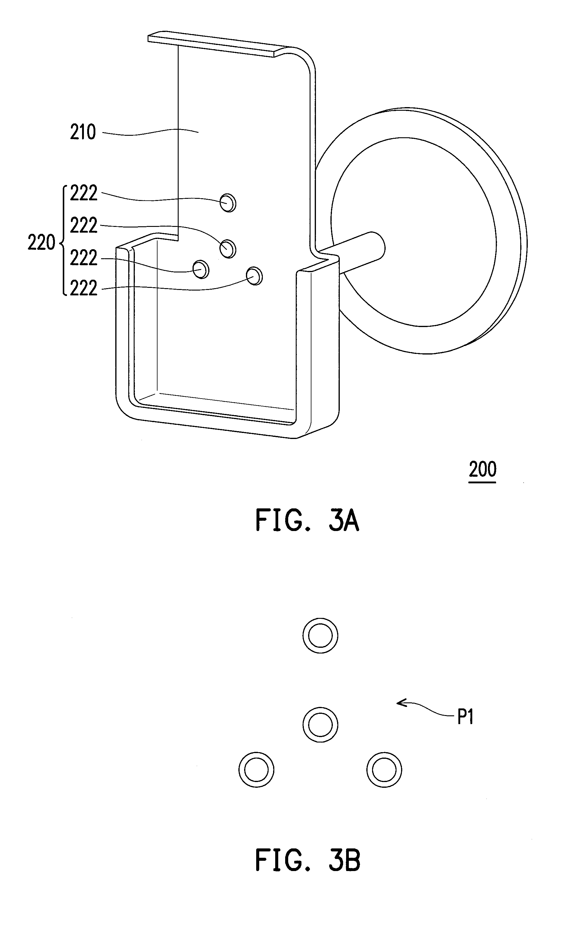
[0038]FIG. 3A is a 3D diagram illustrating an accessory according to the application. FIG. 3B is a schematic diagram of a sensing pattern illustrated in FIG. 3A. Referring to FIG. 3A and FIG. 3B, in the present embodiment, an accessory 200 includes a body 210 and a passive sensing element 220. The passive sensing element 220 is disposed in the body 210 without coupling to any power source element. When the accessory 200 is connected with the electronic device 100, the electronic device 100 is capable of identifying a type of the accessory 200.
[0039]In the present embodiment, the passive sensing element 220 has a plurality of dot-shaped sensing pads 222, and the dot-shaped sensing pads 222 are arranged as a sensing pattern P1, as shown in FIG. 3B. However, in other embodiments, the passive sensing element may include stripe-shaped sensing pads or sensing pads in any other shape to form the sensing pattern, and the application is not limited thereto. When the passive sensing element i...
second embodiment
[0045]FIG. 4A is a 3D diagram illustrating an accessory according to the application. FIG. 4B is a schematic diagram of a sensing pattern illustrated in FIG. 4A. Referring to FIG. 4A and FIG. 4B, in the present embodiment, an accessory 300 includes a body 310 and a passive sensing element 320. The passive sensing element 320 is disposed in the body 310. The passive sensing element 320 has a plurality of dot-shaped sensing pads 322, and the dot-shaped sensing pads 322 are arranged as a sensing pattern P2, as shown in FIG. 4B.
[0046]FIG. 4C is a 3D diagram of connecting the accessory illustrated in FIG. 4A with the electronic device. Referring to FIG. 4A through FIG. 4C, in the present embodiment, when the electronic device 100 is installed on the accessory 300, the active sensing element 130 detects the sensing pattern P2 arranged by the dot-shaped sensing pads 322 so that the processor 120 identifies the type of the accessory 300 according to the sensing pattern P2. In other words, t...
third embodiment
[0048]FIG. 5A is a 3D diagram illustrating an accessory according to the application. FIG. 5B is a schematic diagram of a sensing pattern illustrated in FIG. 5A. Referring to FIG. 5A and FIG. 5B, in the present embodiment, an accessory 400 includes a body 410 and a passive sensing element 420. The passive sensing element 420 is disposed in the body 410. The passive sensing element 420 has a plurality of dot-shaped sensing pads 422, and the dot-shaped sensing pads 422 are arranged as a sensing pattern P3, as shown in FIG. 5B.
[0049]FIG. 5C is a 3D diagram of connecting the accessory illustrated in FIG. 5A with the electronic device. Referring to FIG. 5A through FIG. 5C, in the present embodiment, when the electronic device 100 is installed on the accessory 400, the active sensing element 130 detects the sensing pattern P3 arranged by the dot-shaped sensing pads 422 so that the processor 120 identifies the type of the accessory 400 according to the sensing pattern P3. In other words, t...
PUM
 Abstract
Description
Claims
Application Information