Paint Cup for Spray Gun

a spray gun and paint cup technology, applied in the field of paint cups, can solve the problems of inability to properly control the gap between the cylinder and the exterior and interior cylinders, adversely affecting the function of the ventilation opening, and even making the paint gun unavailable, so as to eliminate undesirable dripping of paint solvents and operate smoothly

Inactive Publication Date: 2014-04-17
LIN CHIN HSIN
View PDF6 Cites 15 Cited by
  • Summary
  • Abstract
  • Description
  • Claims
  • Application Information

AI Technical Summary

Benefits of technology

[0005]Thus, an objective of the present invention is to provide a paint cup for a spray gun to improve the aforementioned problems. The paint cup of the present invention has a vent to atmosphere to prevent a negative pressure from forming in the paint cup and has an accommodating groove to collect paint solvents to eliminate undesirable dripping of the paint solvents from the vent, thereby keeping airflow circulating in the paint cup and allowing the spray gun to be smoothly operated.

Problems solved by technology

However, the gaps between the cylinder part and the exterior and interior cylinders can not be appropriately controlled, so that paint dripping through the labyrinth seal can still occur during shaking of the mixing cup by a user.
Accordingly, the gaps between the cylinders will be narrowed with time, resulting in an adverse impact on the function of the ventilation opening and even making the paint gun unavailable.

Method used


Image

  • Paint Cup for Spray Gun
  • Paint Cup for Spray Gun
  • Paint Cup for Spray Gun

Examples


Embodiment Construction

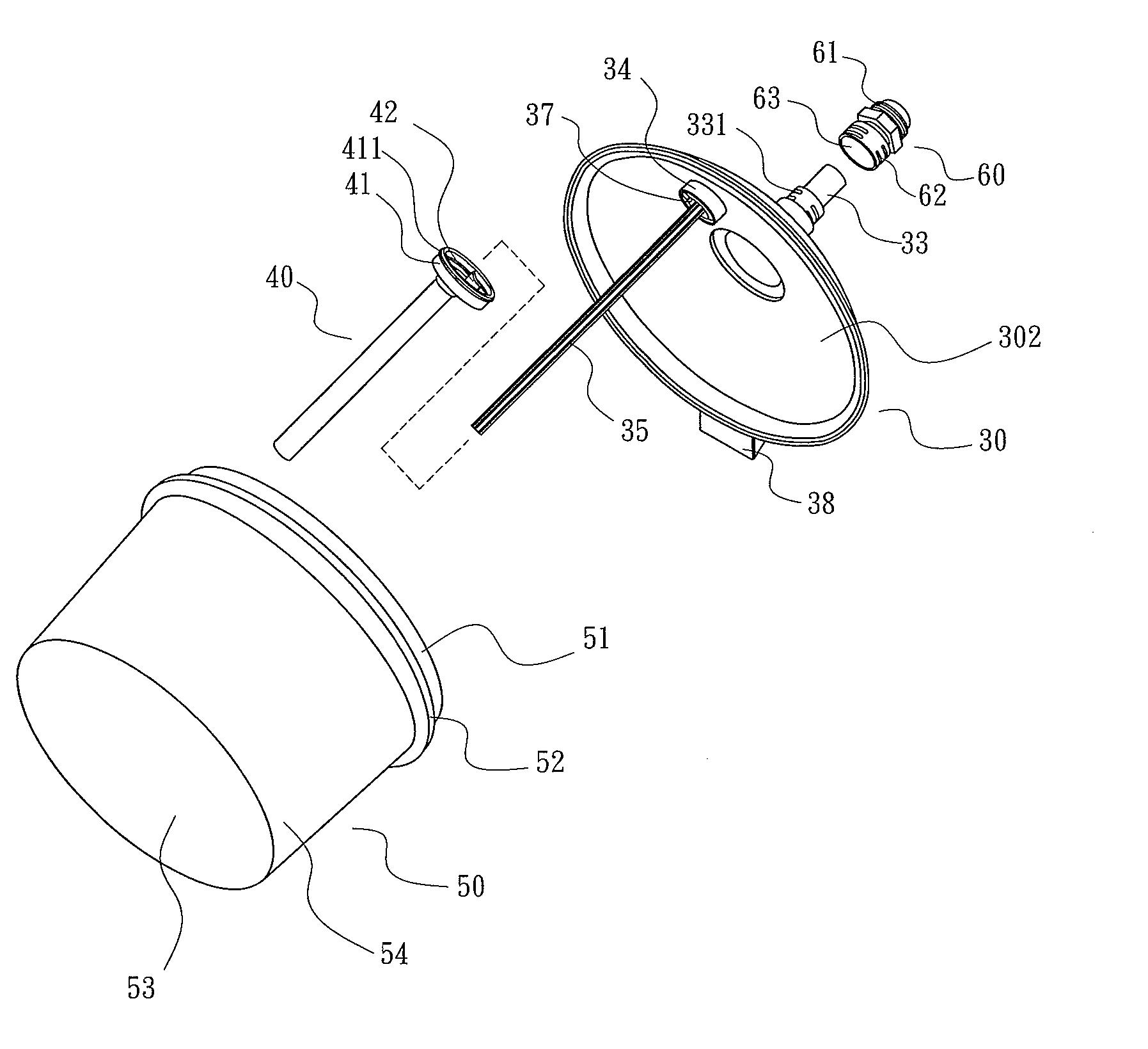
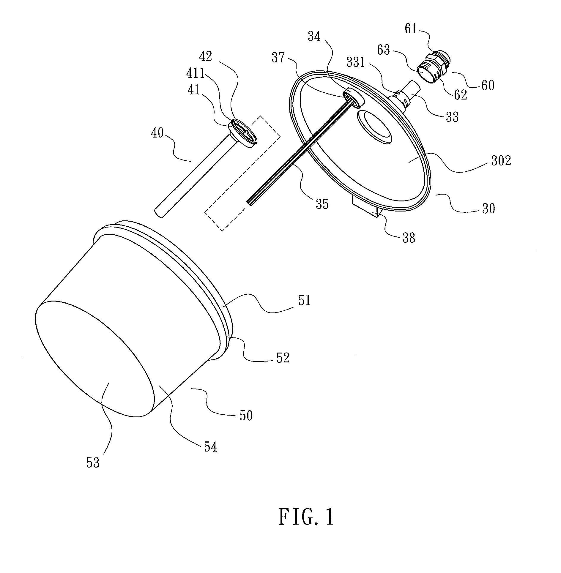
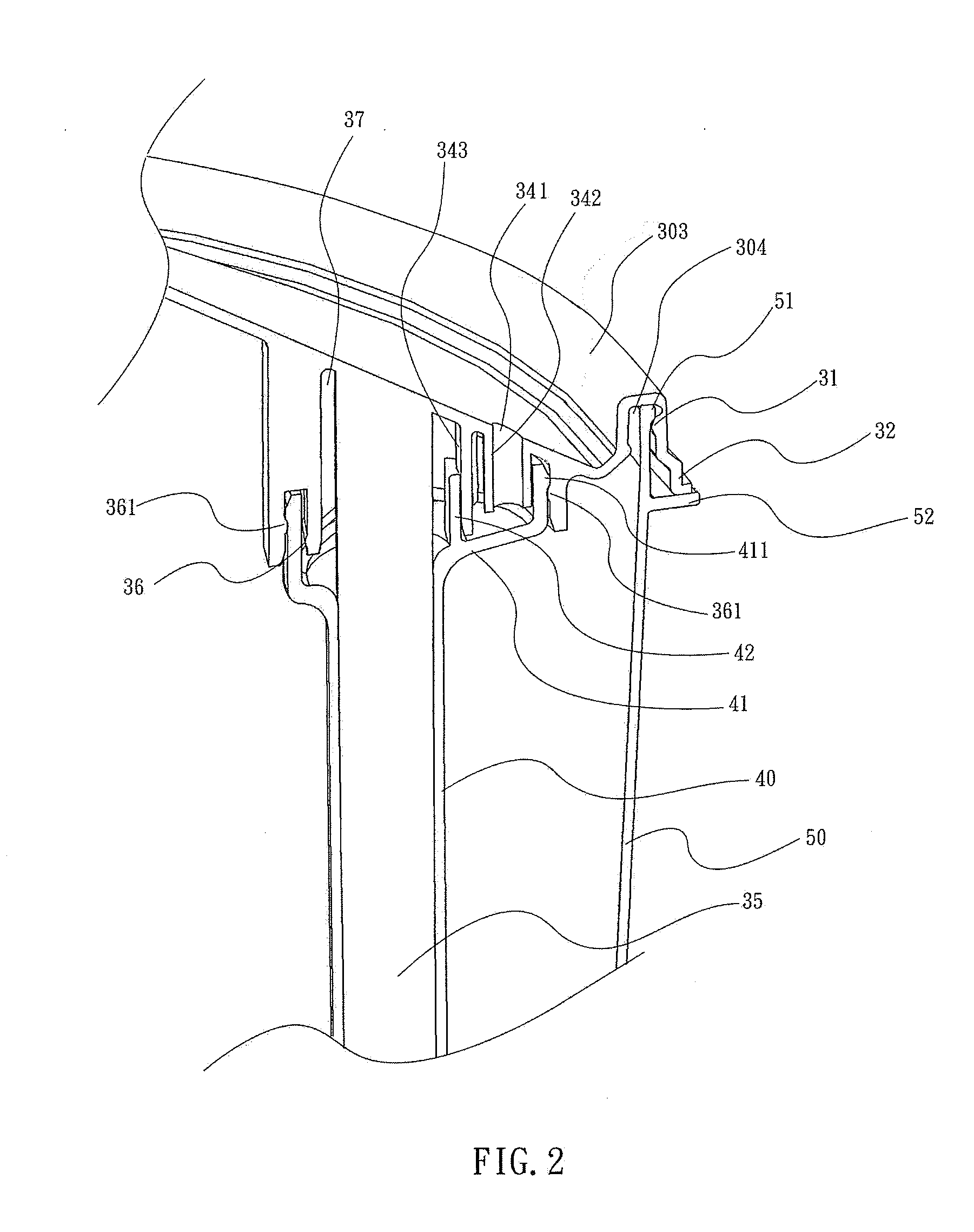
[0018]A paint cup for a spray gun according to the present invention is shown in FIGS. 1 through 7 of the drawings and generally includes a container 50, a lid body 30, and a ventilation member 40. The container 50 is used to contain a material to be sprayed such as paint solvents 80 or the like. The container 50 includes a bottom wall 53, an annular side wall 54 extending upwards from a periphery of the bottom wall 53, and an opening 55 in an upper end thereof. A lip margin 51 is formed on an upper portion of the side wall 54 and around the opening 55. A ledge 52 is protruded outwards from the upper portion of the side wall 54 and adjacent to the opening 55.

[0019]The lid body 30 is used to cover the opening 55 of the container 50 and includes an inner surface 302 facing the container 50 and an outer surface 301 opposite to the inner surface 302. The lid body 30 further includes an annular flange 303 formed on a periphery thereof and having an annular groove 304 therein. An annular ...


PUM


Abstract

A paint cup for a spray gun includes a container containing paint solvents, a lid body covering an upper opening of the container, and a ventilation member mounted in the container. The lid body includes an annular coupling portion protruding from an inner surface thereof, an inner rod located in the annular coupling portion, and a vent extending into an annular coupling groove of the annular coupling portion. A gap is formed between the ventilation member and the inner rod. When the container is turned upside-down, the paint solvents in the gap will flow into an accommodating groove formed between the inner rod and the annular coupling portion, and ambient air circulates in the container via the vent and the gap.

Description

BACKGROUND OF THE INVENTION[0001]1. Field of the Invention[0002]The present invention relates to a paint cup and, more particularly, to a paint cup for a spray gun which features no vent jammed by paint.[0003]2. Description of the Related Art[0004]U.S. Patent Publication No. 2010 / 0301049 A1 discloses a lid for a closeable mixing cup for a paint gun. The lid is provided with a ventilation opening. The ventilation opening is embodied as a labyrinth seal with three cylinders inserted into each other and allowing air to flow. In a preferred embodiment shown, the three cylinders includes an exterior cylinder embodied in one piece with the lid and extending into an interior space of the mixing cup, an interior cylinder provided inside the exterior cylinder and embodied in one piece with the lid, and a snapping part arranged at the bottom end of the exterior and interior cylinders and including a cylindrical part which projects upwards and falls short of an axial length of the exterior and...

Claims


Application Information

Patent Timeline
Patent Type & Authority Applications(United States)
IPC IPC(8): B05B9/03
CPCB05B7/2408B05B7/2478B05B9/0894
Inventor LIN, CHIN-HSIN
Owner LIN CHIN HSIN
Why Eureka
Try Eureka