Lighting apparatus

a technology of lighting apparatus and light source, which is applied in the direction of lighting and heating apparatus, lighting source combinations, instruments, etc., can solve the problems of further examination and achieve the effect of easy control

Active Publication Date: 2014-04-17
ROHM CO LTD
View PDF4 Cites 3 Cited by
  • Summary
  • Abstract
  • Description
  • Claims
  • Application Information

AI Technical Summary

Benefits of technology

[0012]Of various technological features disclosed in the present specification, an object of one technological feature, in light of the above description, is to provide a lighting apparatus that has a useful feature and is easy to control.

Problems solved by technology

However, in connection with the function and control of the lighting apparatus, there are many challenges to be further examined.

Method used


Image

  • Lighting apparatus
  • Lighting apparatus
  • Lighting apparatus

Examples


embodiment 1

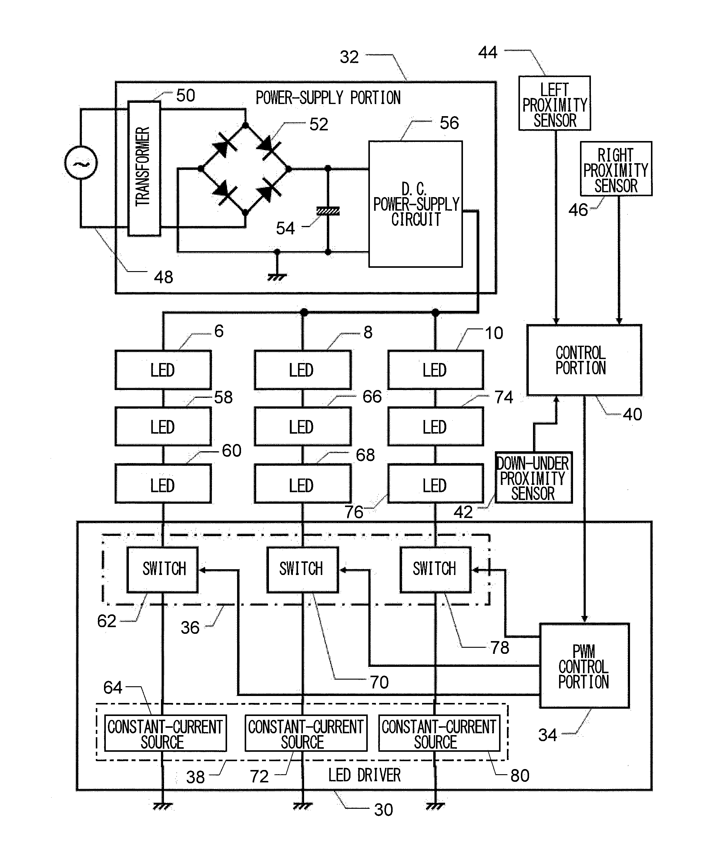
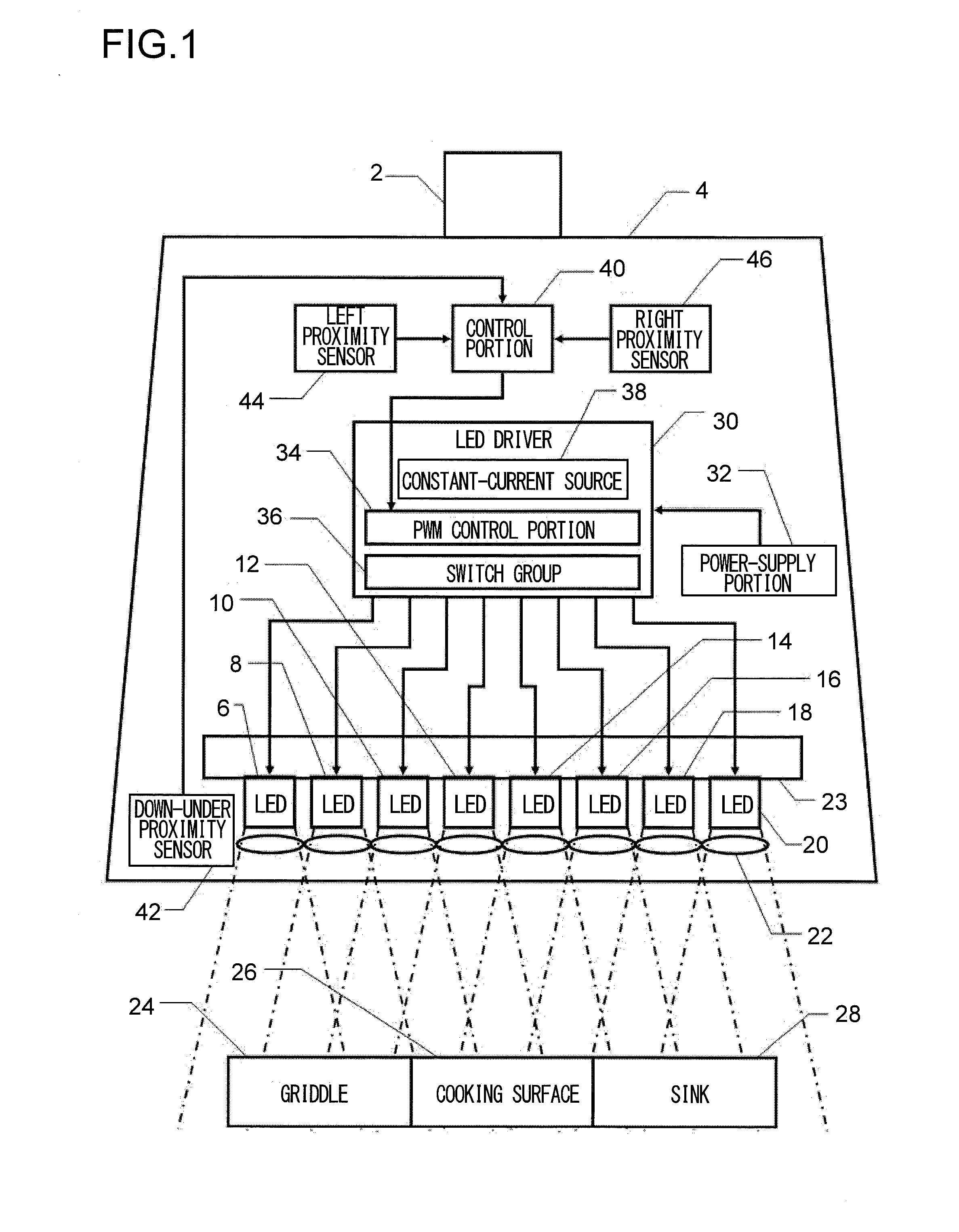
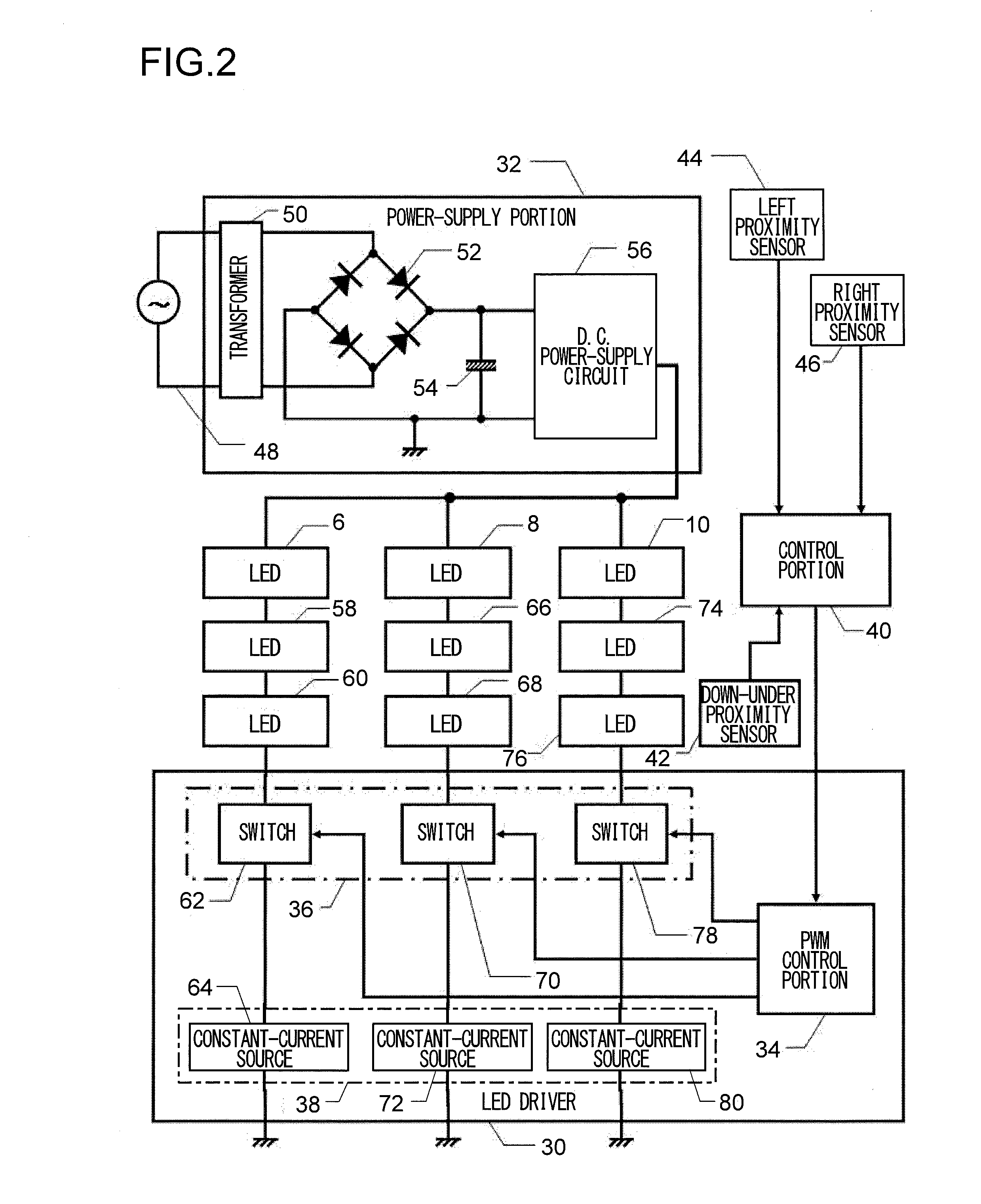
[0029]FIG. 1 is a block diagram of a lighting apparatus according to Embodiment 1 of the present invention. Embodiment 1 is formed as a kitchen cooking area lighting apparatus 4 that is fixed at a suitable upper position of a kitchen by a hold portion 2. Here, the block diagram in FIG. 1 is schematically illustrated for convenience of the understanding; however, if description of an actual structure is necessary, the description is suitably supplemented hereinafter. The lighting apparatus 4 has a plurality of white light emitting diodes (LED) 6, 8, 10, 12, 14, 16, 18 and 20; collects white light, emitted into a relatively wide angle from the diodes, by means of small lens groups of a light collection lens array 22 that is disposed on a front surface; and radiates the light downward. Besides, each white light LED is in thermal contact with a heat radiation plate 23 that is formed of a metal; and prevents deterioration of the light emission efficiency by means of cooling by the heat r...

embodiment 2

[0049]FIG. 6 is a block diagram of a lighting apparatus according to Embodiment 2 of the present invention. Embodiment 2 also is formed as a kitchen cooking area lighting apparatus 104 that is fixed at a suitable upper position of a kitchen by a hold portion 102. Besides, because most of the structure is common to Embodiment 1, the common portions are indicated by reference numbers on the order of 100 with the common second and first digits and description is skipped unless necessary. Besides, the detailed structures shown in FIG. 2 to FIG. 5 are also applicable to Embodiment 2 and other embodiments that are described hereinafter. What Embodiment 2 in FIG. 6 is different from Embodiment 1 in FIG. 1 is a point that white light LEDs 106 to 120 are disposed on an inward bent surface and the light collection lens array 22 disposed in Embodiment 1 is omitted. Because of this, a heat radiation plate 123 also has an inward bent shape.

[0050]As a result of the above structure, even without t...

embodiment 3

[0053]FIG. 8 is a block diagram of a lighting apparatus according to Embodiment 3 of the present invention. Embodiment 3 also is formed as a kitchen cooking area lighting apparatus 204 that is fixed at a suitable upper position of a kitchen by a hold portion 202. Besides, because most of the structure is common to Embodiment 1 and Embodiment 2, the common portions are indicated by reference numbers on the order of 200 with the common second and first digits and description is skipped unless necessary. A first point in which Embodiment 3 in FIG. 8 is different from Embodiment 1 in FIG. 1 or e Embodiment 2 in FIG. 6 is that white light LEDs 208, 212, 216, 220 and the like are evenly mingled with yellow light LEDs 207, 209, 211, 213 and the like.

[0054]And, the white light LEDs 208, 212, 216, 220 and the like are controlled by a white light LED driver 230 that is supplied with electricity by a white light power supply portion 232; independent of this, the yellow light LEDs 207, 209, 211...


PUM


Abstract

Of the various technological features disclosed in the present specification, a structure according to the one technological feature is as follows. A lighting apparatus changeable between an illuminating state and a non-illuminating state comprising: a non-contact motion sensor arranged to sense a movement of a hand near the lighting apparatus; and a controller arranged to control the lighting apparatus in the non-illuminating state to change from the non-illuminating state to the illuminating state in response to the movement of hand sensed by the non-contact motion sensor, and to control the lighting apparatus in the illuminating state to cause a change in illumination with the illuminating state kept in response to the same movement of hand sensed by the non-contact motion sensor.

Description

CROSS-REFERENCE TO RELATED APPLICATIONS[0001]This application is based on the following Japanese Patent Applications, the content of which is hereby incorporated by reference.[0002][1] No. 2010-185826 (the filing date: Aug. 23, 2010)[0003][2] No. 2010-191117 (the filing date: Aug. 27, 2010)BACKGROUND OF THE INVENTION[0004]1. Field of the Invention[0005]The present invention relates to a lighting apparatus.[0006]2. Description of Related Art[0007]Conventionally, various lighting apparatuses are proposed for various purposes. As a light source that is used in a lighting apparatus, a fluorescent lamp is general; however, in recent years, the use of LEDs also is ongoing. Besides, various propositions for control of lighting apparatuses are performed.[0008]For example, a kitchen apparatus is proposed, which on a front surface of a lighting apparatus that serves as a light source when cooking is performed on a top plate, has a switch apparatus composed of a non-contact type sensor such as...

Claims


Application Information

Patent Timeline
Patent Type & Authority Applications(United States)
IPC IPC(8): H05B33/08H05B44/00
CPCH05B33/0842F21V14/04F21V33/0044F21V23/005F21Y2115/10F21Y2107/10F21Y2113/13H05B45/20H05B47/115H05B45/325H05B45/395Y02B20/40F21V29/83F21V3/02F21V23/009F21W2131/30H05K1/189
Inventor NAGASHIMA, MITSUNORITANAKA, MASAHIDE
Owner ROHM CO LTD
Why Eureka
Try Eureka