Lateral ankle fusion plate system and jig, and method for use therewith

a technology of fusion plate and lateral ankle, which is applied in the field of lateral ankle fusion plate system and jig, and the method for using therewith, can solve the problems of inability to provide one or more of the desired precision, stability, fixation, etc., and achieves the effects of convenient implanting, stable, strong, and comfortable for patients

Active Publication Date: 2014-04-17
ORTHOHELIX SURGICAL DESIGNS
View PDF14 Cites 60 Cited by
  • Summary
  • Abstract
  • Description
  • Claims
  • Application Information

AI Technical Summary

Benefits of technology

[0007]An object of the present disclosure is therefore to provide a system for ankle fusion which improves upon the short-comings of the prior art and to provide novel systems and methods for immobilizing the joints between the tibia, talus and the calcaneus of a human patient that makes it possible to perform arthrodesis under good operating conditions while also making it possible to obtain bone fusion that is particularly stable, strong, precise, and comfortable for the patient.
[0008]Another object of the present disclosure is to provide novel systems and methods for immobilizing the joints between the tibia, talus, and the calcaneus of a human patient that is particularly successful under all conditions of bone quality or pathology.
[0009]Another object of the present disclosure is to provide novel systems and methods for immobilizing the joints between the tibia, talus, and the calcaneus of a human patient that is relatively easy to

Problems solved by technology

While such devices exist, each is lacking in providing one or more of the desired precision, stabili

Method used


Image

  • Lateral ankle fusion plate system and jig, and method for use therewith
  • Lateral ankle fusion plate system and jig, and method for use therewith
  • Lateral ankle fusion plate system and jig, and method for use therewith

Examples


Embodiment Construction

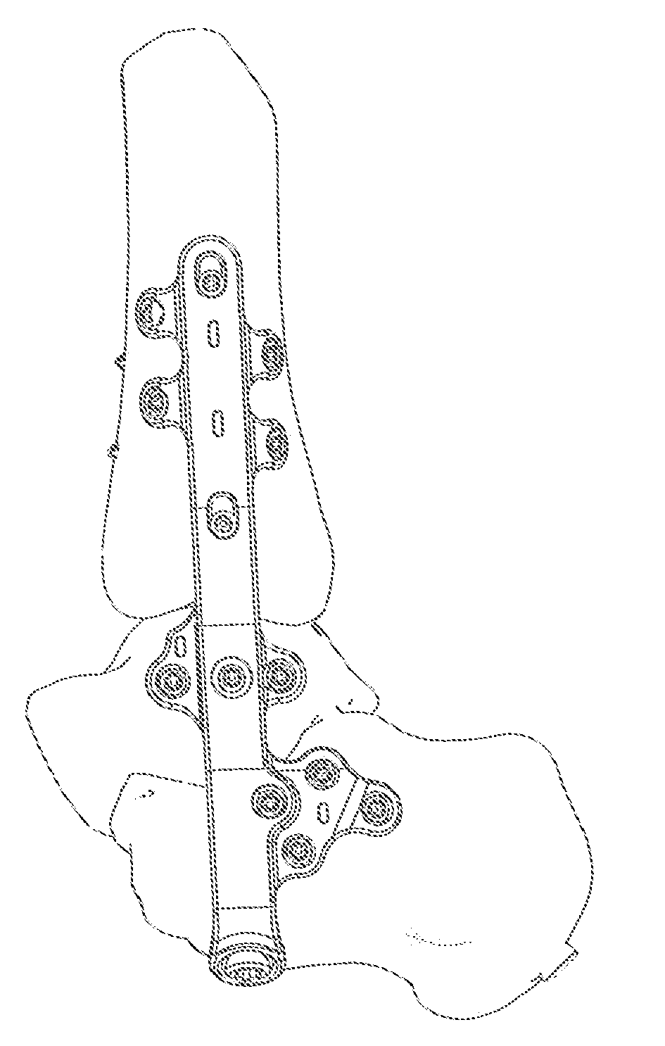
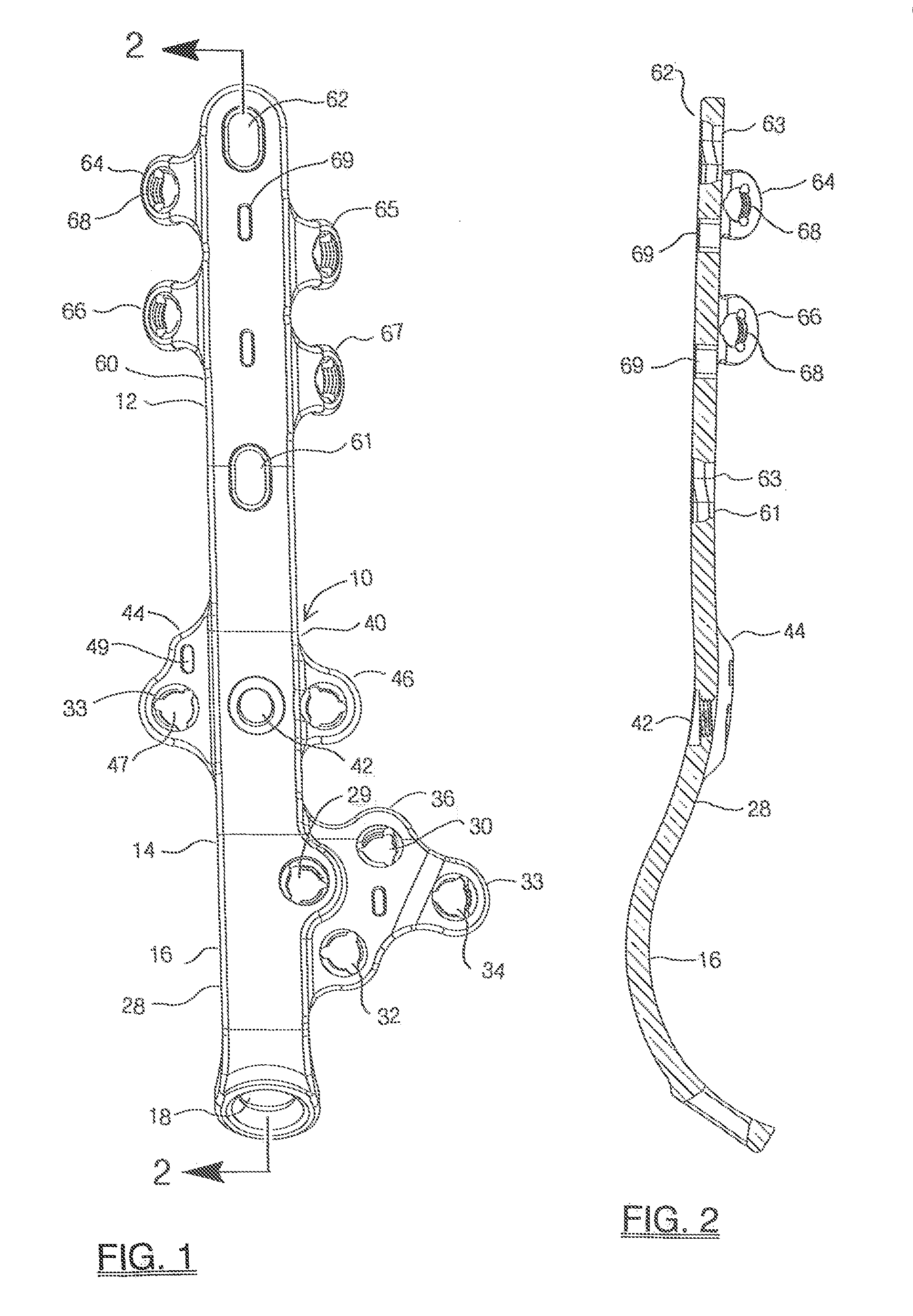
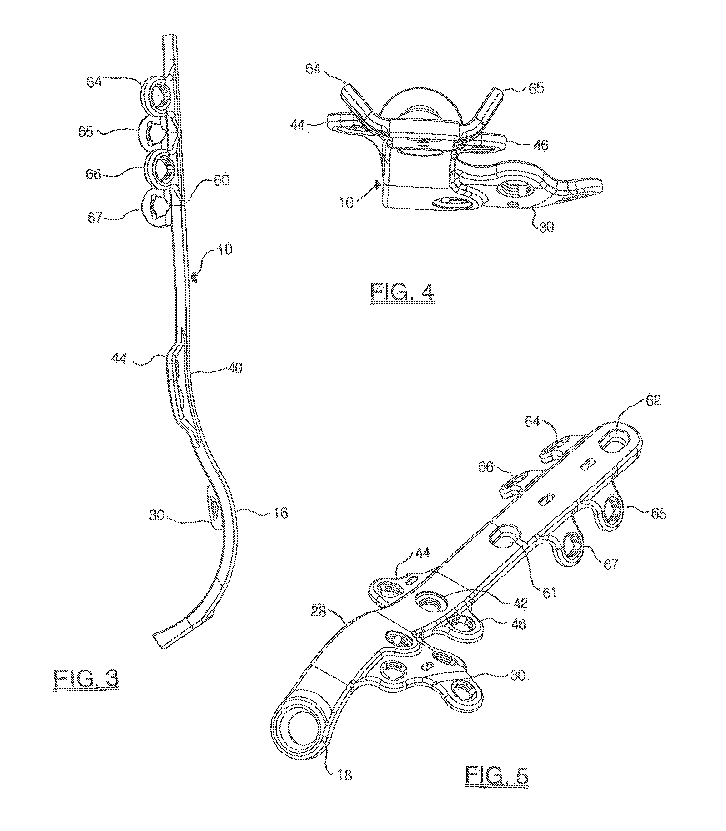
[0035]FIG. 1 illustrates a side view of a lateral ankle fusion plate 10 in accordance with the present invention. The plate 10 has a central rail member 12 with a first segment 14 that abuts the calcaneus. This segment has a C-shaped portion or stirrup 16 (i.e. along the longitudinal axis) that wraps under the inferior surface of the calcaneus. The curve is a compound curve that forms about 70°+ / −10°, or more preferably 5°, of a circle and having a radius of from about 0.74 to about 0.84 inch+ / −0.1 inch such that the terminal screw hole 18 in the calcaneal position is about 1.8 inch+ / 0.25 inch from the posterior screw hole in the talar segment. The plate has a length from the axis of the central screw hole of the talar segment in the tibial terminus of about 3 inches+ / −025 inch.

[0036]The central axis 18′ of the screw hole 18 forms an angle of from about 30° to about 60°, and preferably at about 40° to about 50°, and most preferably at about 42° to about 47° to a medial line in that ...


PUM


Abstract

The invention comprises a lateral ankle fusion plate, a jig for use with the fusion plate and a method for ankle fusion of the joints between the tibia, the talus, and the calcaneus. In addition, a separate fusion screw from posterior to anterior through the calcaneal tuberosity into the distal tibia is useful and can be placed using the targeting jig of the invention. The plate includes a C-shaped stirrup portion that wraps the bottom of the calcaneus and is provided with a screw hole for a T-T-C-fusion screw. A C-shaped targeting jig is provided that interfaces with the plate to allow for placement of the calcaneal screw and has an additional attachment for placement of the independent fusion screw so as to avoid impingement with the plate, and plate screws. The invention also relates to a method of surgery that incorporates the use of the plate, the jig and the tibial/talar/calcaneal fusion screw for an arthrodesis of the ankle joint.

Description

FIELD OF THE INVENTION[0001]The present disclosure relates to an invention which involves an ankle fusion plate system, a jig for use with the fusion plate system and a method for ankle fusion, i.e. arthrodesis, where the joints between the tibia, the talus, and the calcaneus of a human patient can be immobilized using a lateral implant alone, or in combination with a separate fusion screw from posterior to anterior through the calcaneal tuberosity into the distal tibia. The plate includes a C-shaped stirrup portion that wraps the bottom of the calcaneus and is provided with a screw hole for the placement of a relatively vertical screw (i.e., relative to the lower leg, i.e., in the sagittal plane from inferior to superior) through the articular capsule of the talocalcaneal joint and the tibiotalar joint and which secures the calcaneus, the talus and the tibia together. An independent 50-100 mm fusion screw can be used with the lateral plate to augment the immobilization by multiplan...

Claims


Application Information

Patent Timeline
IPC IPC(8): A61F2/30A61F2/42
CPCA61F2/4202A61F2/30749A61B17/1728A61B17/1739A61B17/808A61B17/8061A61B17/1775
Inventor JENG, CLIFFORD L.HEAVENER, JACKSON R.MYERSON, MARKDEN HARTOG, BRYAN D.SAN GIOVANNI, THOMAS
Owner ORTHOHELIX SURGICAL DESIGNS
Why Eureka
Try Eureka