
Product Dispensing System

a product and product technology, applied in the field of processing systems, can solve the problems of generating a relatively limited number of products, requiring extensive changes to mechanical/electrical/software systems, and additional components to be added

Active Publication Date: 2014-04-17
DEKA PROD LLP
View PDF14 Cites 52 Cited by
  • Summary
  • Abstract
  • Description
  • Claims
  • Application Information

AI Technical Summary

Benefits of technology

The present invention relates to a system and method for controlling the selection and distribution of products in a product dispensing system. The system includes a user interface for prompting the selection of a product, a machine control processor, a power distribution module, and a power supply unit. The machine control processor controls the distribution of the product through a solenoid pump, which pumps fluid from a product container during each stroke. The system also includes a current sensor for sensing the current flow through the solenoid coil and a control logic subsystem for monitoring the flow conditions of the fluid. The control logic subsystem uses the measured current flow through the solenoid coil to determine whether the stroke of the solenoid pump is functional or non-functional, and to determine whether the product container is a Sold-Out condition. The system can also determine the amount of fluid remaining in the product container using an RFID tag that stores a fuel gauge value. The invention provides a more efficient and effective way to control the selection and distribution of products in a product dispensing system.

Problems solved by technology

Unfortunately, such systems are often static in configuration and are only capable of generating a comparatively limited number of products.
While such systems may be capable of being reconfigured to generate other products, such reconfiguration may require extensive changes to mechanical / electrical / software systems.
Such extensive modifications may be required due to existing devices / processes within the processing system being non-reconfigurable and having a single dedicated use, thus requiring that additional components be added to accomplish new tasks.

Method used


Image

  • Product Dispensing System
  • Product Dispensing System
  • Product Dispensing System

Examples


Embodiment Construction

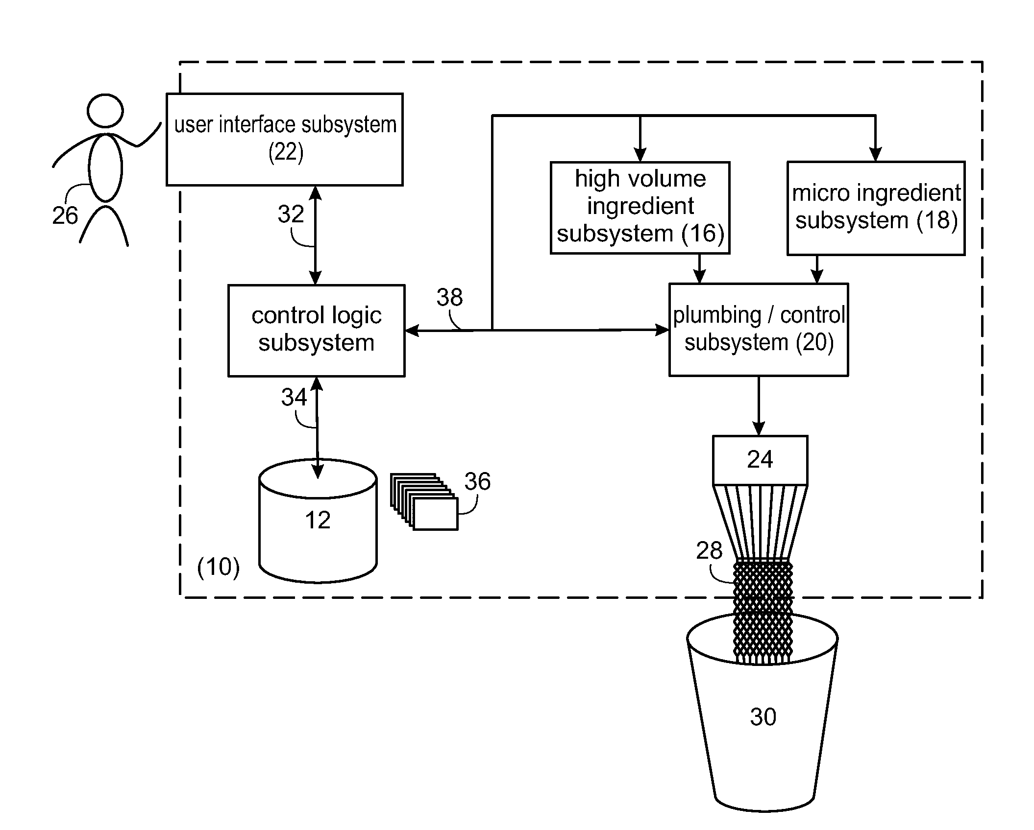
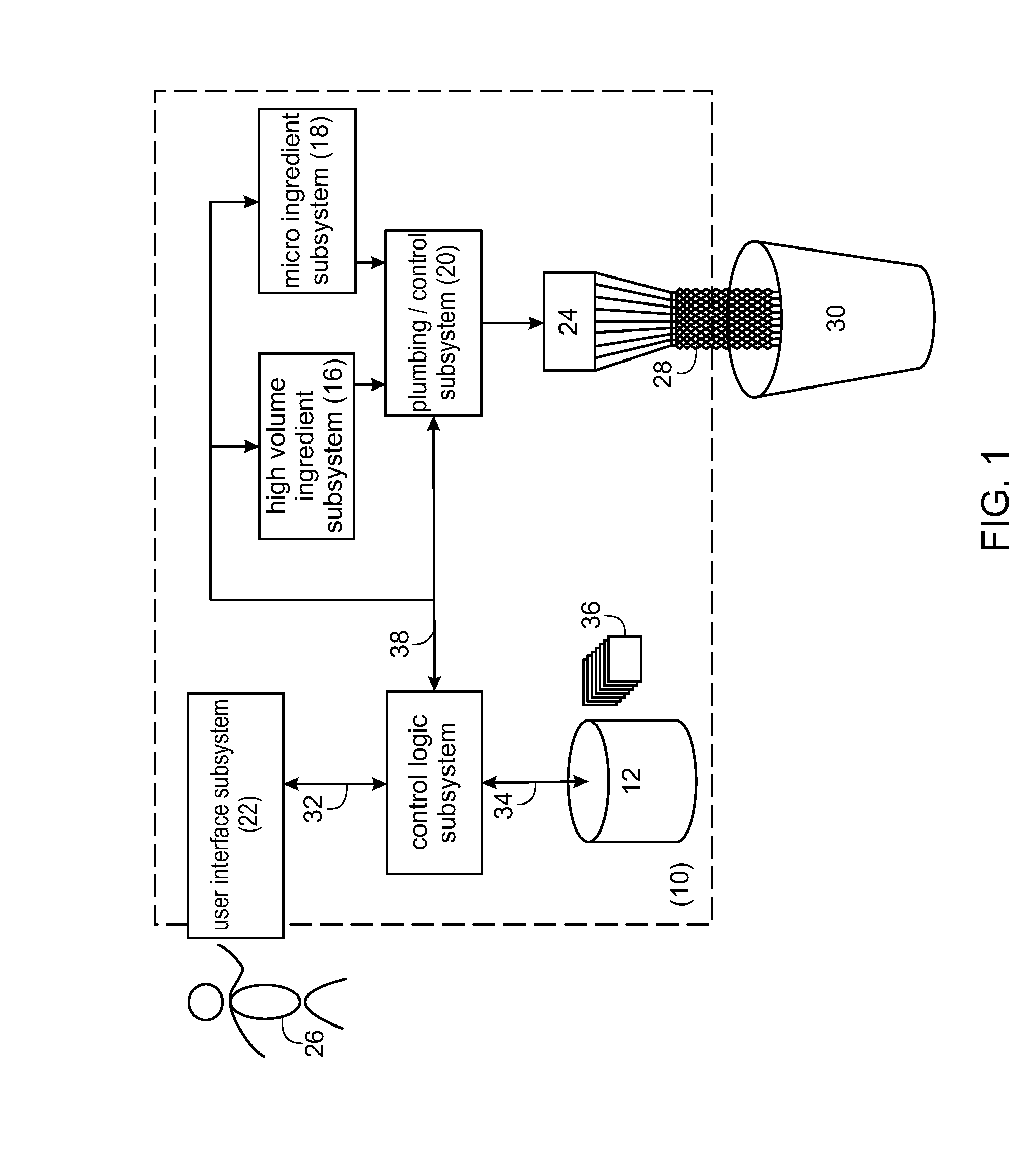
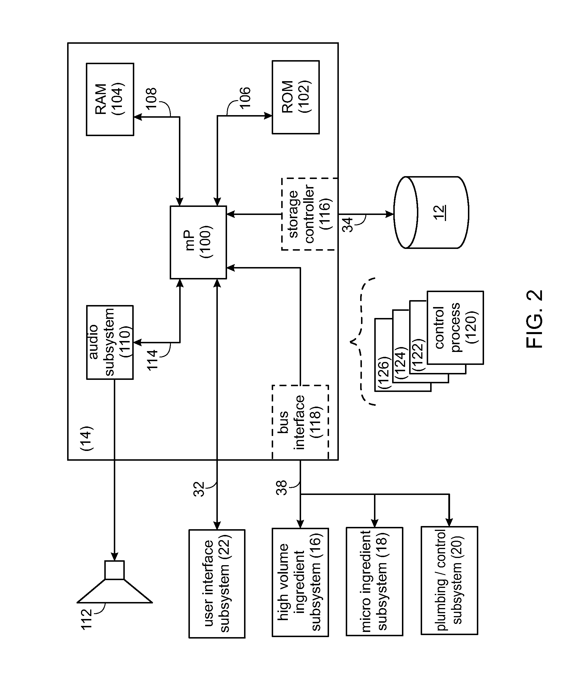
[0113]Described herein is a product dispensing system. The system includes one or more modular components, also termed “subsystems”. Although exemplary systems are described herein, in various embodiments, the product dispensing system may include one or more of the subsystems described, but the product dispensing system is not limited to only one or more of the subsystems described herein. Thus, in some embodiments, additional subsystems may be used in the product dispensing system.

[0114]The following disclosure will discuss the interaction and cooperation of various electrical components, mechanical components, electro-mechanical components, and software processes (i.e., “subsystems”) that allow for the mixing and processing of various ingredients to form a product. Examples of such products may include but are not limited to: dairy-based products (e.g., milkshakes, floats, malts, frappes); coffee-based products (e.g., coffee, cappuccino, espresso); soda-based products (e.g., floa...


PUM


Abstract

A system for controlling selection and distribution of a product in a product dispensing system. The system includes a user interface for prompting a selection and selecting the product, a machine control processor in communication with the user interface, a power distribution module connected to the machine control processor, and a power supply unit for supplying power to the system through the power distribution module.

Description

CROSS REFERENCE TO RELATED APPLICATIONS[0001]The present application is a Continuation-In-Part of U.S. patent application Ser. No. 13 / 662,102, filed Oct. 26, 2012 and entitled Product Dispensing System (Attorney Docket No. J70), which claims priority to U.S. Provisional Patent Application Ser. No. 61 / 552,938 filed Oct. 28, 2011 and entitled Product Dispensing System (Attorney Docket No. 182); U.S. Provisional Patent Application Ser. No. 61 / 560,007 filed Nov. 15, 2011 and entitled Product Dispensing System (Attorney Docket No. J13); and U.S. Provisional Patent Application Ser. No. 61 / 636,298 filed Apr. 20, 2012 and entitled Product Dispensing System (Attorney Docket No. J39), each of which is hereby incorporated herein by reference in its entirety.[0002]U.S. patent application Ser. No. 13 / 662,102, filed Oct. 26, 2012 and entitled Product Dispensing System (Attorney Docket No. J70), is also a Continuation-In-Part of U.S. patent application Ser. No. 13 / 339,962, filed Dec. 29, 2011, now...

Claims


Application Information

Patent Timeline
Patent Type & Authority Applications(United States)
IPC IPC(8): B67D7/22
CPCB67D7/221B67D1/0036G01F3/10G01F3/20B67D2210/00034B67D2210/0006B67D1/0892G01F23/804
Inventor BIASI, JOHN J.BEAVIS, RUSSELL H.GOULET, MICHAEL J.PRIBYL, ERIC L.
Owner DEKA PROD LLP
Features
  • Generate Ideas
  • Intellectual Property
  • Life Sciences
  • Materials
  • Tech Scout
  • Unparalleled Data Quality
  • Higher Quality Content
  • 60% Fewer Hallucinations
Learn More