Surgical staple and staple pocket for forming kidney-shaped staple

a technology of staple pocket and surgical staple, which is applied in the field of surgical staple pocket and staple pocket for forming kidney-shaped staples, can solve the problems of poor hemostatic effect, machining and mounting of instruments, and poor sealing of stapled tissue, and achieve the effect of facilitating sealing and bleeding stoppage of edges and facilitating surrounding tissue healing

Active Publication Date: 2014-04-24
CHANGZHOU KANGDI MEDICAL STAPLER
View PDF9 Cites 35 Cited by
  • Summary
  • Abstract
  • Description
  • Claims
  • Application Information

AI Technical Summary

Benefits of technology

[0010]An objective of the present invention is to provide surgical staple and staple pocket for forming kidney-shaped staple, so that a back span and two legs of an staple form an M-shaped staple, and a staple pocket comprises a side surface, a bottom surface, and an oblique ridge that are formed after the staple pocket is inward recessed on the tissue contacting surface of a staple anvil. Therefore, when tissue varying in thickness is stapled by using staples of the same height, each staple driver pushes the M-shaped staple out of the staple cartridge, and urge

Problems solved by technology

Larger size of the rings 16 and 17 facilitates healing of surrounding tissues, but results in poor sealing of the stapled tissue and a poor hemostatic effect.
In order to achieve the surgical effect, staple cartridges loaded with U-shaped staples having legs of different heights and/or a staple anvil provided with staple pockets in different depths are required to be adopted, the surgical staples and the staple pockets of this kind of surgical stapler increase the difficulty in machining and mounting of the instrument, thereby increasing the cost of the instrument.
The specifications of the staple cartridge loaded with U-shaped staples having legs of different heights are limited, and normally for each difference of 0.5 mm in the tissue clamping th

Method used


Image

  • Surgical staple and staple pocket for forming kidney-shaped staple
  • Surgical staple and staple pocket for forming kidney-shaped staple
  • Surgical staple and staple pocket for forming kidney-shaped staple

Examples


Embodiment Construction

[0066]Preferred embodiments of surgical staple and staple pocket for forming kidney-shaped staple according to the present invention are described below through examples with reference to the accompanying drawings. The scope of the present invention is specified by the claims. It should be known that some or all of the accompanying drawings are schematic drawings for illustrating the preferred embodiments of the present invention, and do not illustrate the real size of what is shown. By referring to the detailed descriptions of the preferred embodiments, the above and other objectives and advantages of the present invention may be better understood.

[0067]The processes of various surgical staples and staple pockets for forming kidney-shaped staples according to embodiments of the present invention are described below with reference to FIG. 14 to FIG. 40, so as to illustrate effects of the kidney-shaped surgical staples and the staple pockets.

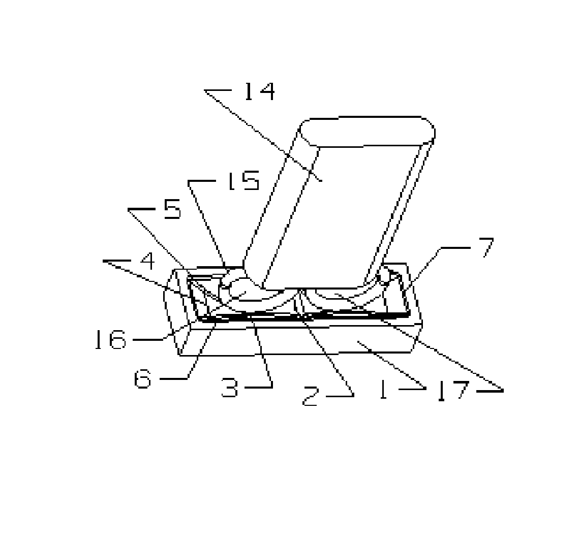
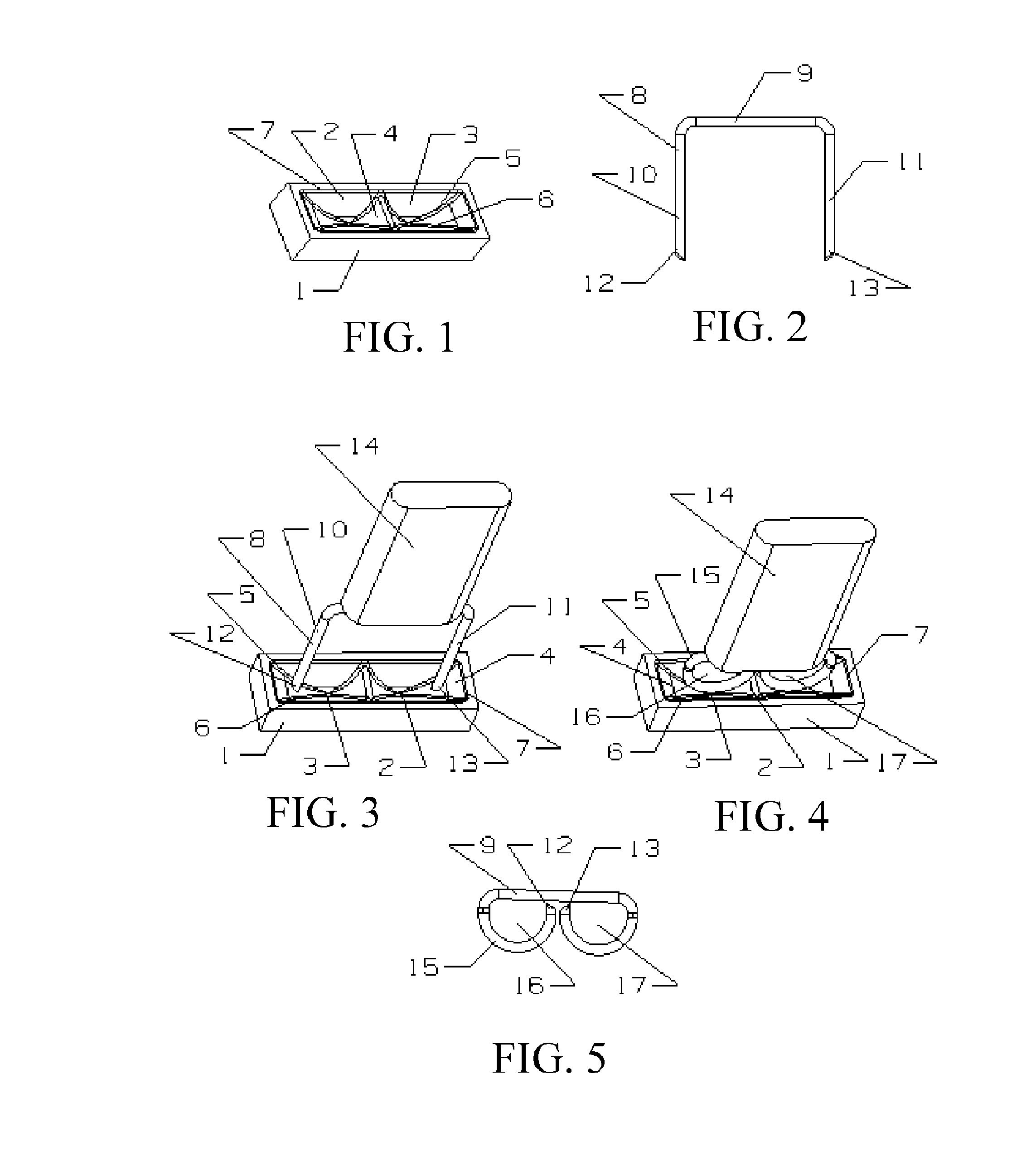
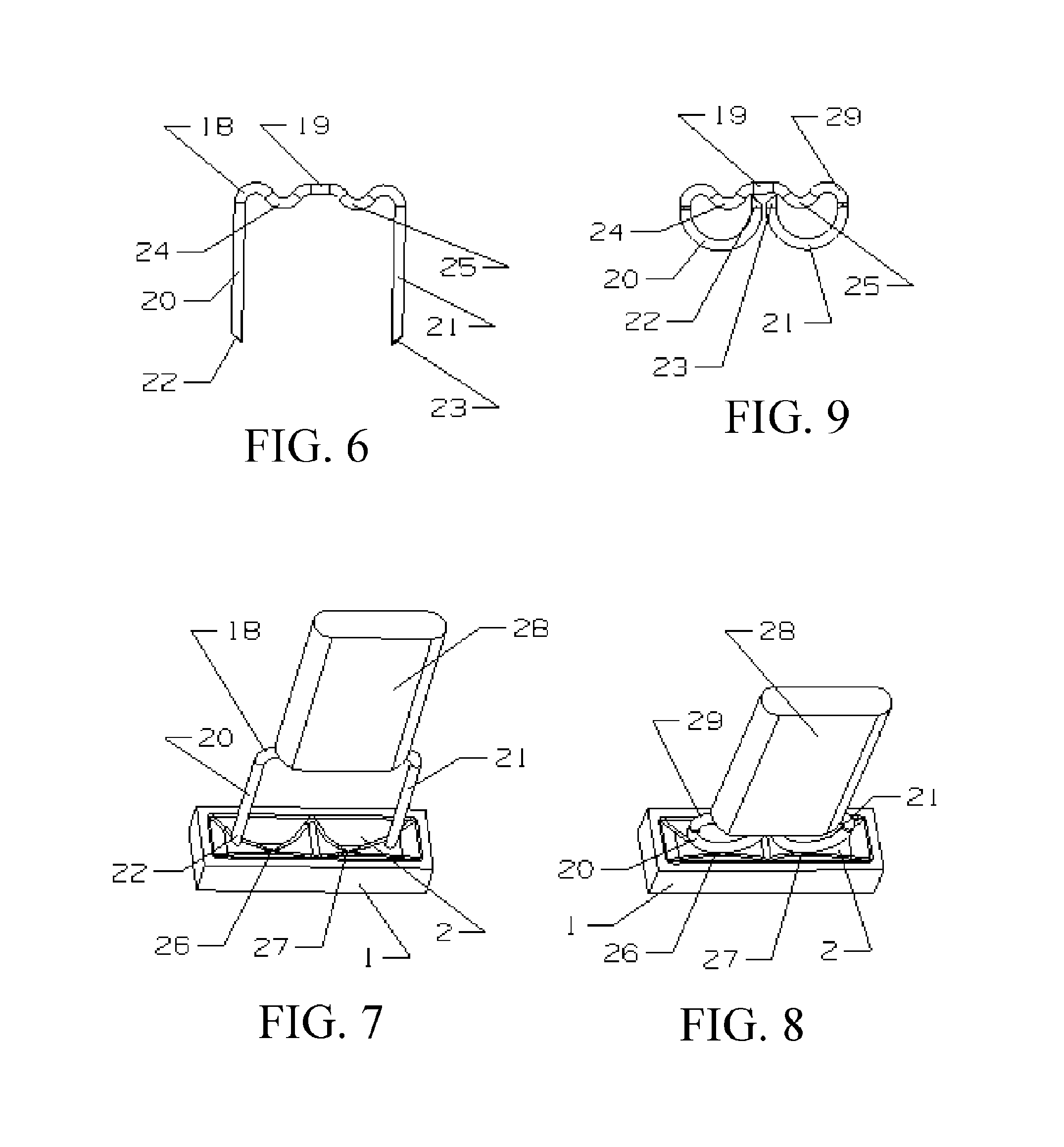
[0068]As shown in FIG. 14, an staple 50 ar...


PUM

PropertyMeasurementUnit
Fractionaaaaaaaaaa

Abstract

The present invention disclosed a surgical staple (50) and staple pocket (57) for forming kidney-shaped staple therefor, with the staple pocket (57) being recessed inward on the tissue contacting surface of the staple anvil (58), and with M-shaped staple (50) being used, wherein the degree of projection of the middle portion of the back span (51) of the M-shaped staple (50) arranged at the inner circle or arrangd at a proximal side of a cutter slot (121) is larger than that of the back span (51) of the M-shaped staple (50) arranged at the outer circle or arranged at a distal side of the cutter slot (121), so that when the staple (50) of the same height are adapted to staple tissues to be stapled of different thickness, staple driver (68) bends the M-shaped staple (50) on the staple pocket (57) to form kidney-shaped staple (50) so as to achieve the operational effect of being able to seal the stapled tissue, to stop bleeding and to heal the tissue therearound.

Description

BACKGROUND OF THE PRESENT INVENTION [0001]1. Field of Invention[0002]The present invention relates to surgical staples and staple pockets used in various surgical staplers, and more particularly to surgical staple and staple pocket for forming kidney-shaped staple.[0003]2. Description of Related Arts[0004]Various surgical staplers used for replacing needles and thread, for manual stapling, in surgery are widely used in surgery such as end-end, end-side, and side-side stapling of organs and tissues including human digestive tract organs, respiratory tract organs, and urogenital organs, in surgery for forming a channel, and in surgery for closing a cut, and are particularly suitable for staples where organs and tissues are exposed and difficult to operate, so as to reduce operative time and improve quality of surgery.[0005]As described in US Patent Publication No. 20070194082 and 20090255978, various well-known staple shaping mechanisms of surgical staplers each mainly include: a stap...

Claims


Application Information

Patent Timeline
IPC IPC(8): A61B17/068
CPCA61B17/068A61B17/0644A61B17/07207A61B17/1155A61B2017/07264
Inventor ZHANG, ZURENYANG, WEI MINLI, SUYINGJIANG, ZHENYUYUAN, DONGKUNYU, GUOANJI, RONGZHANG, YIYIXU, WEIHUA
Owner CHANGZHOU KANGDI MEDICAL STAPLER
Why Eureka
Try Eureka