
Methods and devices for optimising rendering of an encrypted 3D graphical object

a technology of encrypted 3d objects and rendering methods, applied in the field of 3d models, can solve the problems of affecting the quality of the game, the difficulty of ensuring the integrity of the game,

Active Publication Date: 2014-04-24
INTERDIGITAL CE PATENT HLDG
View PDF7 Cites 14 Cited by
  • Summary
  • Abstract
  • Description
  • Claims
  • Application Information

AI Technical Summary

Benefits of technology

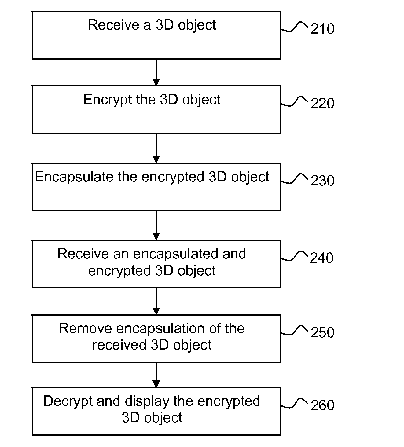
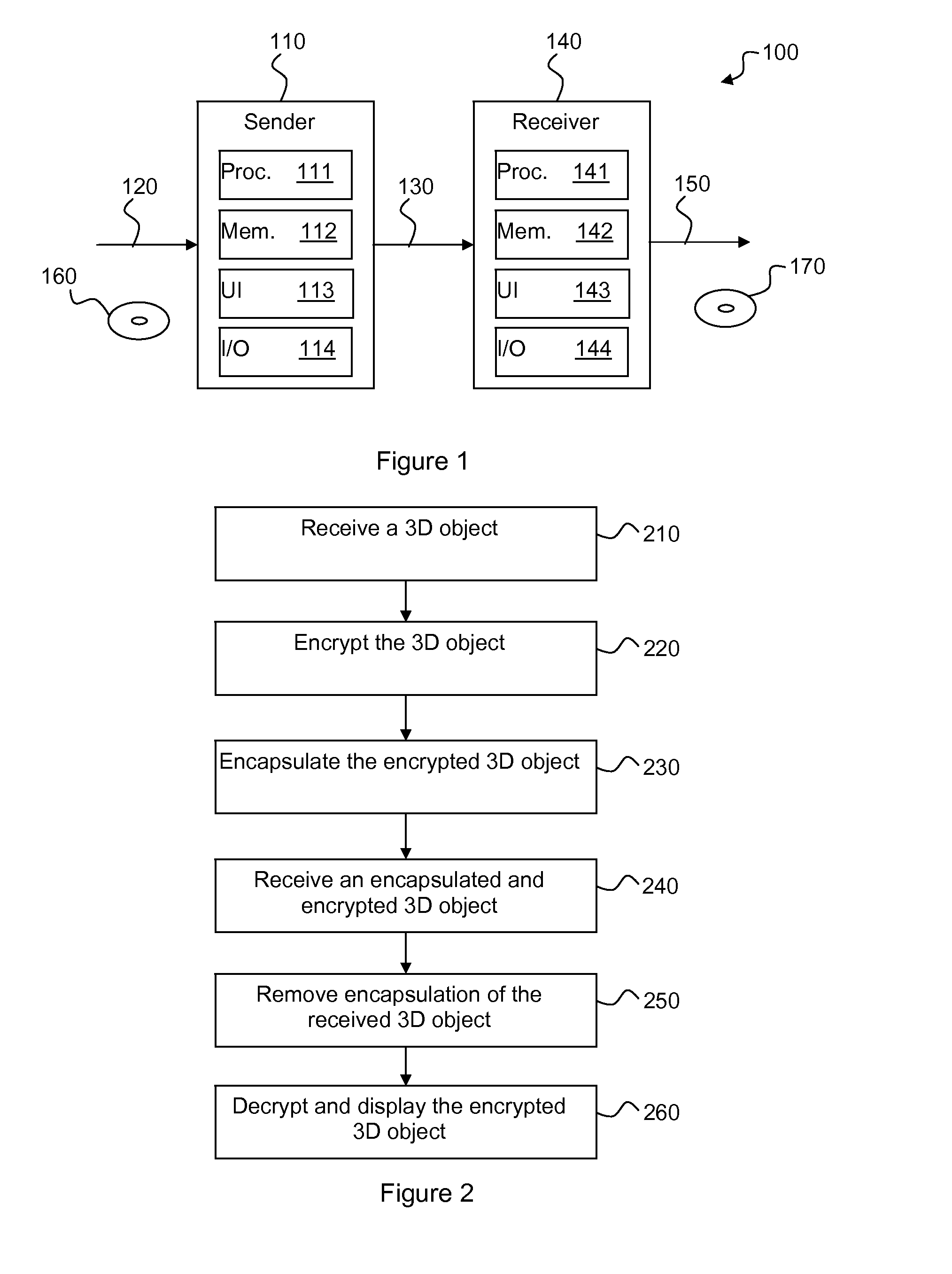
The invention is about a device and method for encrypting and decrypting three-dimensional graphical objects. The device receives the encrypted object and removes the encapsulation, which is a list of surfaces that enclose the object. The method then decrypts the object to obtain the unencrypted object. The technical effects of the invention include improved data security and efficient data management.

Problems solved by technology

Building an experienced character within an online game is a very lengthy process that can require hundreds of hours behind the keyboard.
Leaking the 3D model for a scene of the next blockbuster from Hollywood studios may result in bad press for the studios.
As the surfaces now are defined by other node values, the encrypted 3D object usually becomes quite random and ‘chaotic’.
Once again, the encrypted 3D object usually becomes quite random and ‘chaotic’.

Method used


Image

  • Methods and devices for optimising rendering of an encrypted 3D graphical object
  • Methods and devices for optimising rendering of an encrypted 3D graphical object

Examples


first preferred embodiment

Added Surfaces Defined by Existing Points

[0044]In a first preferred embodiment, a number s surfaces are added to the 3D object 120. These new surfaces are defined using the existing points. This may be illustrated as follows:

PointsSurfaces11. . .n points. . .m surfaces, indexes 1 . . . nnmm + 1. . .s surfaces, indexes 1 . . . nm + s

[0045]When providing the encapsulated object of the first preferred embodiment, it is necessary also to provide to the receiver the number s of added surfaces in order for the receiver to be able to remove the added surfaces during decapsulation. The number s may be sent using any suitable side channel, such as for example as metadata in the 3D object or in a specific field in a license linked to the 3D object.

second preferred embodiment

Added Surfaces Defined by Added Points

[0046]In a second preferred embodiment, a number s surfaces defined using a set of p added points are added to the protected object, as follows:

PointsSurfaces11. . .n points. . .m surfaces, indexes 1 . . . nnmn + 1m + 1. . .p points. . .s surfaces, indexesn + pn + 1 . . . n + pm + s

[0047]Naturally, it will be appreciated that it is possible to define some added surfaces using one or two initial points as long as at least one added point is used.

[0048]When providing the encapsulated object of the second preferred embodiment, it may also be necessary to provide to the receiver the number p of additional points to be able to retrieve the set of added surfaces. Indeed, the added surfaces are the only surfaces that use the added points (indices from n+1 to n+p). During decapsulation, the set of p points and the set of s surfaces are removed. As in the first preferred embodiment, any suitable side channel can be used to provide the value p. However, i...

third preferred embodiment

Using a Null Surface as a Tag

[0049]In the third preferred embodiment, s new surfaces defined using the existing points of the protected object are added and a “fake” surface, acting as a tag, is inserted to separate the original set of surfaces from the new surfaces. The fake surface is a null surface defined by the same point index for all its defining points (e.g. three for a triangle). In many cases, the receiver may easily detect this “fake” surface and thus extract the original surfaces.

[0050]However, some environments naturally produces this kind of null surfaces. In this variant, a new point is added so as to differentiate the added “fake” null surface from the natural null surfaces. This new point is added to the set of points of the encrypted object.

[0051]The resulting encapsulated object can be described as:

PointsSurfaces11n pointsm surfaces, indexes 1 . . . nnmn + 11 pointm + 11 surface: (n + 1, n + 1, n + 1)m + 2s surfaces, indexes 1 . . . nm + s + 1

[0052]When providing ...


PUM


Abstract

The graphical characteristics of 3D graphical objects encrypted using format-preserving encryption makes rendering of such objects quite inefficient by non-authorized devices. To optimise the rendering of a three-dimensional graphical object represented by a list of points and a list of surfaces defined by points in the list of points, a device receives the graphical object; encrypts the graphical object using a format-preserving encryption method to obtain an encrypted graphical object; encapsulates the encrypted graphical object to obtain an encapsulated graphical object by adding at least one encapsulation by adding for each encapsulation, to the list of surfaces, a plurality of surfaces that together enclose the encrypted graphical object and, in an embodiment, at least one point to the list of points; and outputs the encapsulated graphical object. Decryption is performed by essentially reversing the encryption.

Description

[0001]This application claims the benefit, under 35 U.S.C. §119 of European Patent Application 12306311.7, filed Oct. 23, 2012.TECHNICAL FIELD[0002]The present invention relates generally to 3-D models and in particular to the protection of graphical objects of such models.BACKGROUND[0003]This section is intended to introduce the reader to various aspects of art, which may be related to various aspects of the present invention that are described and / or claimed below. This discussion is believed to be helpful in providing the reader with background information to facilitate a better understanding of the various aspects of the present invention. Accordingly, it should be understood that these statements are to be read in this light, and not as admissions of prior art.[0004]The use of three-dimensional (3D) graphical objects has been increasing in the last years, particularly with the emergence of metaverses. There are multiple usages for 3D objects: socializing worlds, games, mirrorin...

Claims


Application Information

Patent Timeline
Patent Type & Authority Applications(United States)
IPC IPC(8): G06F21/60
CPCG06F21/602G09C5/00G06T17/00
Inventor MAETZ, YVESELUARD, MARC
Owner INTERDIGITAL CE PATENT HLDG
Learn More