Relief valve for overload protection

a technology of overload protection and relief valve, which is applied in the direction of valve operating means/releasing devices, functional valve types, transportation and packaging, etc., can solve the problems of increasing water resource waste, increasing water resource shortage, and affecting the performance of sealing of the plug, so as to improve the sliding effect, the effect of sealing the outlet and ensuring the performance of the plug

Active Publication Date: 2014-05-01
ZHUHAI BOW KITCHEN & BATH PRODS
View PDF9 Cites 2 Cited by
  • Summary
  • Abstract
  • Description
  • Claims
  • Application Information

AI Technical Summary

Benefits of technology

[0025](7) The plug of the relieve valve for overload protection of the present invention is a convex stage with an increasing sectional area from the top down, and an O-shaped sealing ring or a flat gasket is disposed underneath the convex stage. Such structure may realize a better sealing of the outlet, and the performance of sealing of the plug is further ensured by using the O-shaped sealing ring or the flat gasket.
[0026](8) A fixing sleeve disposed between the guide pillar and the slidable sleeve, and on the outer side of the guide pillar, is able to realize a better sliding effect and a better sealing effect by working with the slidable sleeve of the relieve valve for overload protection of the present invention.
[0027](9) The elastic member of the relieve valve for overload protection of the present invention is a spring, one end of which is disposed on the shoulder and the other end is secured on the valve body. The spring presses the slidable sleeve on the valve body, so as to ensure a compact overall structure of the valve, so as to prevent the slidable sleeve from wobbling.

Problems solved by technology

People cannot live without water.
With the development of modern society, shortage of water resource is becoming increasingly severe, and water saving has become a topic of great concern.
Under such circumstances, valves at water circuit terminals need to bear certain water pressure, and if a valve is damaged, the water in it will rush out, causing huge amount waste of water resource.
If not handled timely, this will not only lead to huge amount waste of water resource, but also cause damage to other assets.
However, while this kind of valve is applied in water circuit, a relatively high pressure is generated by water at one end of the valve mandrel when the valve is opened, because water is in its liquid state and does not diffuse as fast as high pressure gas, and this pressure cannot be released as the overflow holes are relatively small, so that the valve mandrel is apt to move upward as a result of the water pressure, thus blocking the outlet.
Therefore, this valve is not suitable for being applied in water circuit control.
Besides, after the valve mandrel blocks the outlet, the pressure is mainly concentrated at the top of the valve mandrel with a relatively small area of stress, this may provide enough force in high pressure gas circuit, however, in normal water circuit, because of the relatively small area of stress, the force provided is relatively weak, thus cannot seal the outlet firmly, and the reliability of the system is decreased.

Method used


Image

  • Relief valve for overload protection
  • Relief valve for overload protection
  • Relief valve for overload protection

Examples


embodiment 1

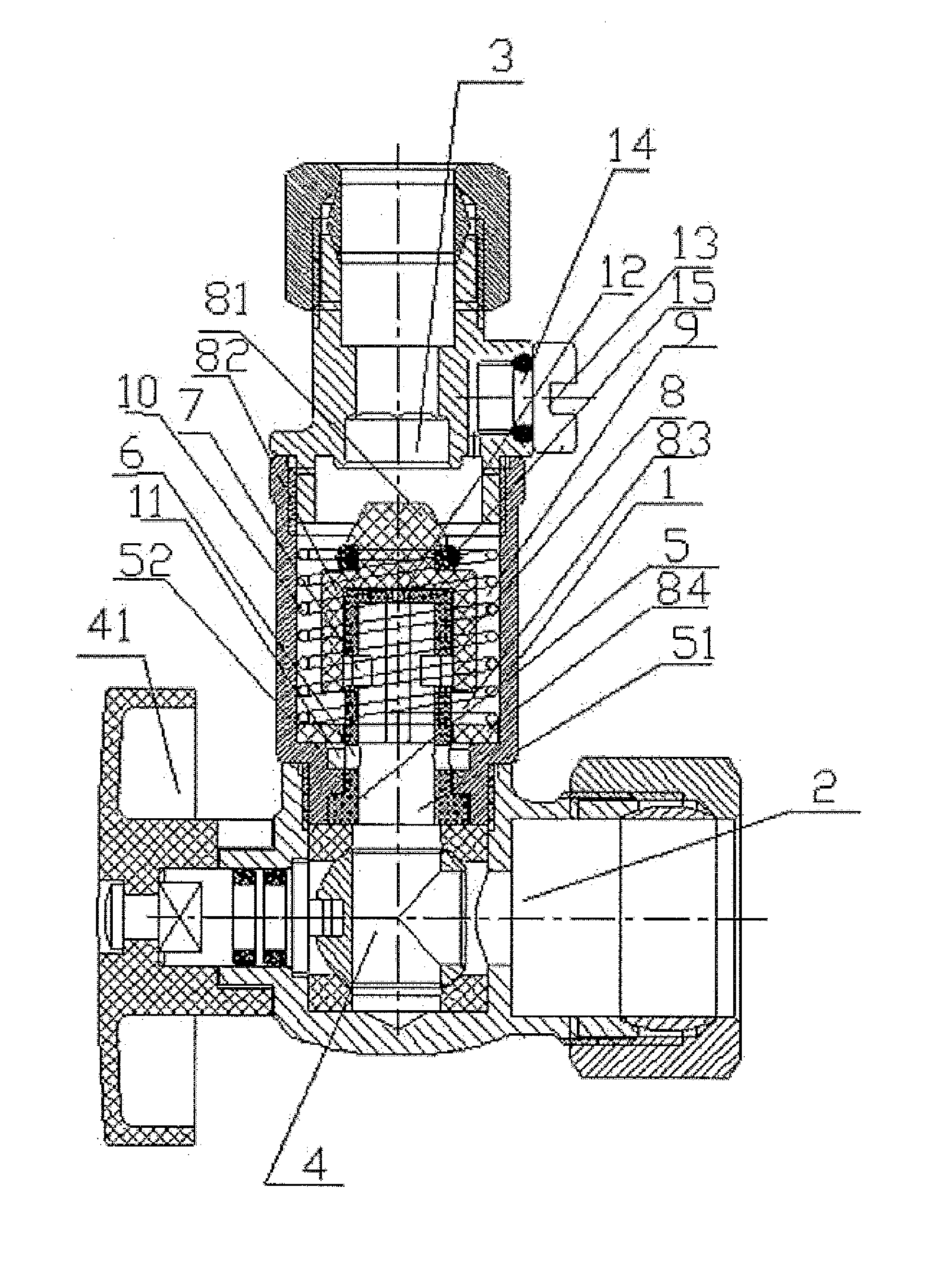
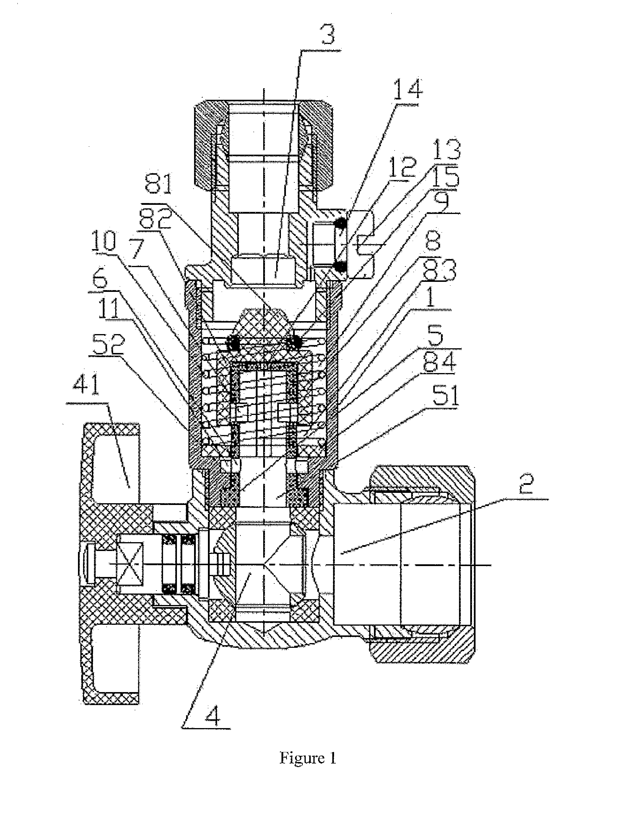
[0034]The relieve valve for overload protection of the present invention, as shown in FIG. 1, comprises a valve body 1 provided with a valve cavity, an inlet 2 and an outlet 3 disposed on each side of the valve body 1 respectively. The relieve valve for overload protection in this embodiment is an angle valve, with the inlet 2 and the outlet 3 forming a right angle, which is used for connection at a turning position. Other valves with the inlet 2 and the outlet 3 connected in a straight line may also be applied. A switching member is disposed at the inlet 2 and inside the cavity. The switching member here in this embodiment is a ball valve 4 controlled through a handle 41. A hollow guide pillar 5 is in sealed connection with the ball valve 4 and communicating internally with the inlet 2 through the ball valve 4, and is provided with a first water outlet 6 and a second water outlet 7 disposed in the direction of water flowing. Two first water outlets 6 and two the second water outlet...

embodiment 2

[0038]The slidable sleeve 8, when moving up and down along the guide pillar, comprises three states of:

[0039]initial state: as shown in FIG. 1, the shoulder 84 of the slidable sleeve 8 is pressed on the valve body 1 by the elastic member, and the shoulder 84 of the slidable sleeve 8 is in sealed connection with the external wall of the guide pillar 5 and the internal wall of the valve body 1. The sealed connection here in this embodiment ensures that enough pressing force is provided to the shoulder 84 of the slidable sleeve 8 when the switching member is opened. Even if there is tiny clearances between the shoulder 84 and the internal wall of the valve body 1 (or the external wall of the guide pillar), the function of the structure will not be influenced, although the moving speed of the slidable sleeve 8 will be lower when the valve is initially opened. Initially, the second water outlet 7 on the guide pillar 5 is sealed by the sliding wall 82, and the plug 81 on the top of the sl...

embodiment 3

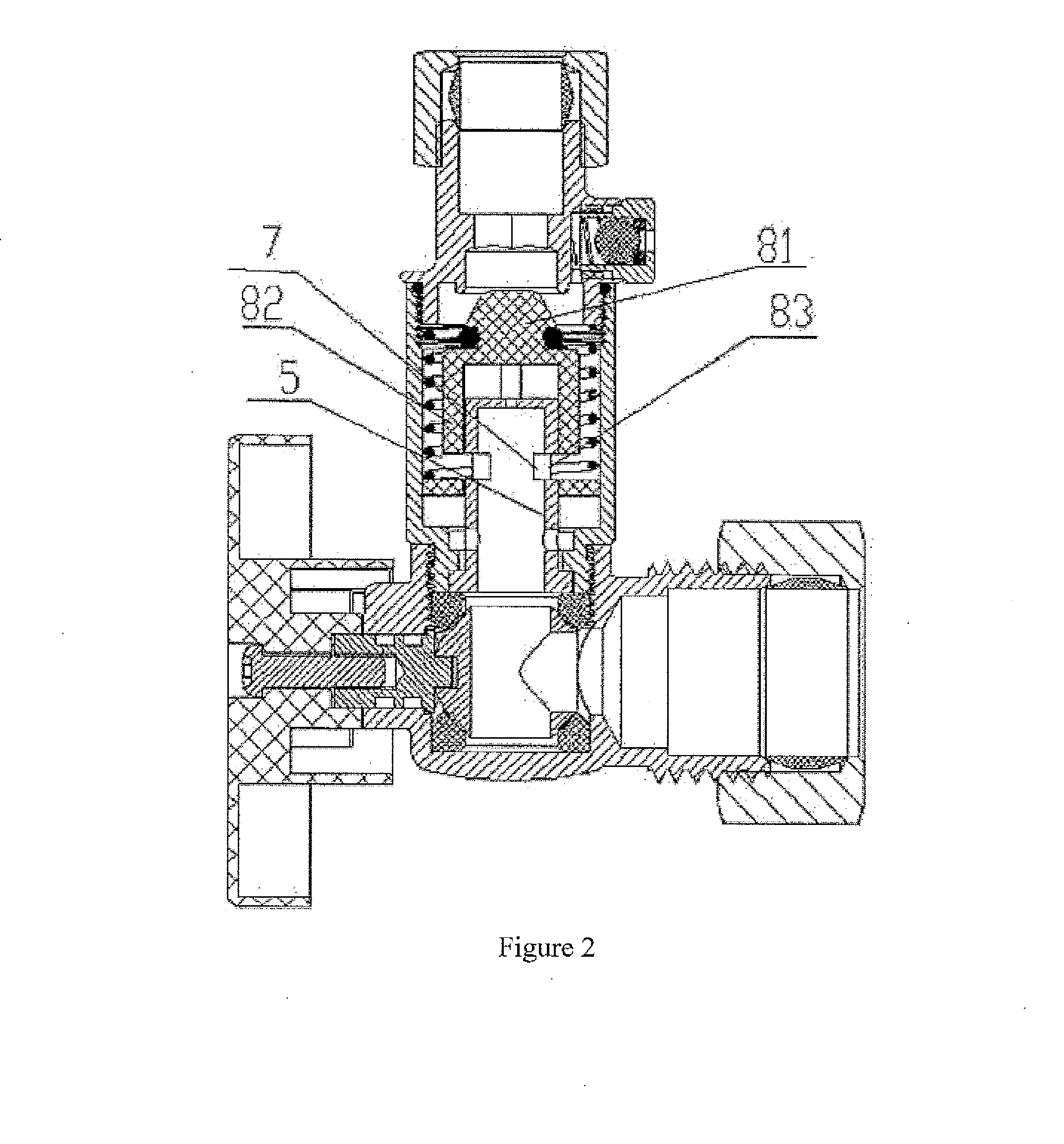
[0043]In order to ensure that the slidable sleeve 8 can move upward smoothly to a position that the osculum 83 on the sliding wall 82 communicates with the second water outlet 7 of the guide pillar 5, through providing enough pressing force on the slidable sleeve 8 when the ball valve 4 is opened, a top water outlet 12 is disposed on the top of the guide pillar 5. In order to provide better sliding sealing effect of the slidable sleeve 8 on the guide pillar 5, a fixing sleeve 52 is disposed between the guide pillar 5 and the slidable sleeve 8, and on the outer side of the guide pillar 5. The shape of the fixing sleeve 52 is in correspondence with the guide pillar 5, thus ensures that the slidable sleeve 8 is able to slide smoothly up and down thereon in a sealed manner. In order to ensure the sealing effect of the plug 81 on the top of the slidable sleeve 8, the plug 81 is a convex stage with an increasing sectional area from the top down, and an O-shaped sealing ring 15 is disposed...


PUM


Abstract

A relief valve for overload protection includes a switching member disposed at the inlet, and a guide pillar in sealed connection with the switching member. The guide pillar is provided with a first water outlet and a second water outlet disposed in the direction of water flowing, and a slidable sleeve is disposed on an outer side of said guide pillar. When the water pipe connected to the outlet cracks, the water pressure at said outlet may drop, which leads to further movement of said slidable sleeve towards the outlet and cause the plug disposed on the top of said slidable sleeve to plug the outlet in a sealed manner, thus closing the outlet.

Description

TECHNICAL FIELD[0001]This invention relates to a relieve valve for overload protection, in particular, a relieve valve for overload protection used in water circuit control, which is able to close automatically when the corresponding water pipe is ruptured.BACKGROUND TECHNOLOGY[0002]Water is an important kind of natural resource in people's life. People cannot live without water. With the development of modern society, shortage of water resource is becoming increasingly severe, and water saving has become a topic of great concern. When water is used in daily life, water supply system is established with water supply circuits, and switching valves are disposed at water circuit terminals to control water flow. Under such circumstances, valves at water circuit terminals need to bear certain water pressure, and if a valve is damaged, the water in it will rush out, causing huge amount waste of water resource. If not handled timely, this will not only lead to huge amount waste of water re...

Claims


Application Information

Patent Timeline
Patent Type & Authority Applications(United States)
IPC IPC(8): F16K17/02
CPCF16K17/02F16K5/061F16K17/10F16K17/168F16K17/30F16K17/34Y10T137/7794
Inventor YUAN, XUNPINGTANG, ZHIQIANG
Owner ZHUHAI BOW KITCHEN & BATH PRODS
Why Eureka
Try Eureka