Loop thermosyphon cooling device

Inactive Publication Date: 2014-05-01
COOLING HOUSE
View PDF14 Cites 18 Cited by
  • Summary
  • Abstract
  • Description
  • Claims
  • Application Information

AI Technical Summary

Benefits of technology

[0006]Therefore, it is a primary objective of the present invention to provide a loop thermosyphon cooling device having a communication assembly coupled between the evaporation pipe and the condensation pipe, so th

Problems solved by technology

However, LEDs will generate a large amount of heat, so that it is necessary to add a cooling device at the high bay lamp to assist the effect of dissipating the heat generated by the LEDs.
In addition, places such as machine rooms having equipment like mainframe computers, servers or instruments installed therein may accumulate lots of heat after a long time of the operation, so that the cooling device is required to prevent the equipment from being damaged and achieve the heat dissipation effect.
However, the aforementioned loop cooling device has the following drawbacks: more loop heat pipe

Method used


Image

  • Loop thermosyphon cooling device
  • Loop thermosyphon cooling device
  • Loop thermosyphon cooling device

Examples


Example

[0029]The technical contents of the present invention will become apparent with the detailed description of preferred embodiments accompanied with the illustration of related drawings as follows. It is noteworthy that the drawings are provided for the purpose of illustrating the present invention, but not intended for limiting the scope of the invention.

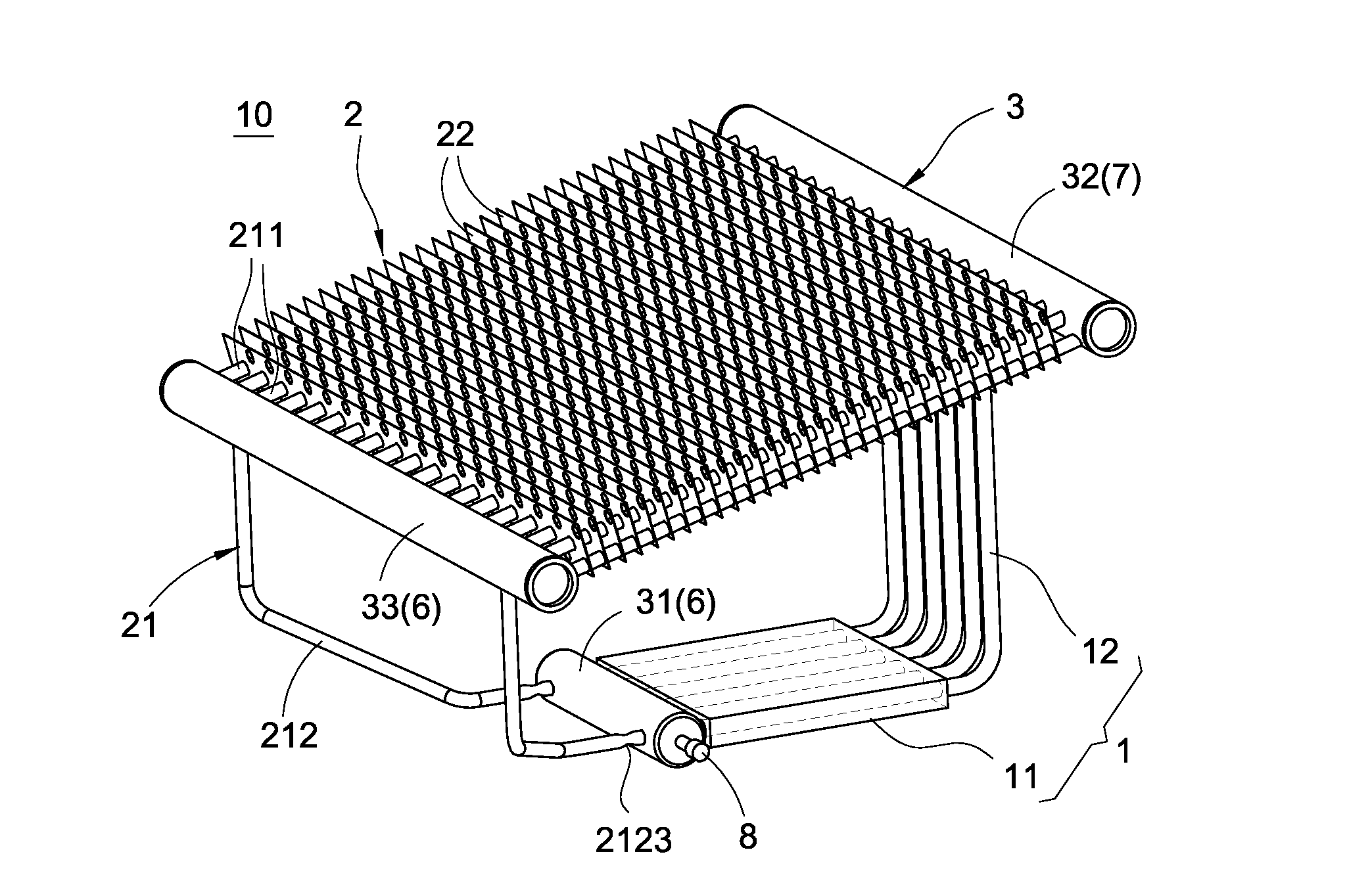
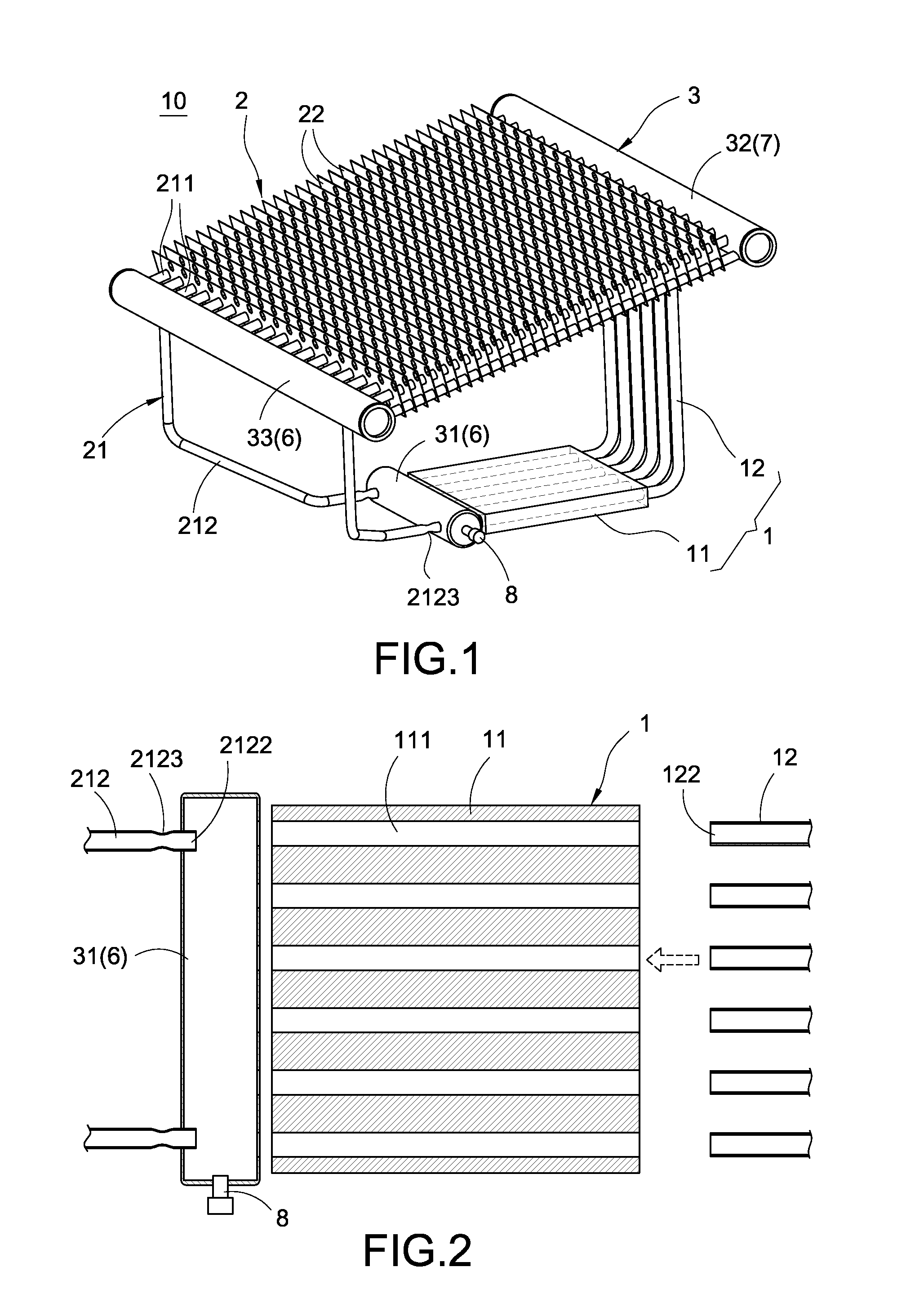
[0030]With reference to FIGS. 1 to 7 for a loop thermosyphon cooling device of the present invention, the thermosyphon cooling device 10 comprises an evaporator 1, a condenser 2 and a communication assembly 3.

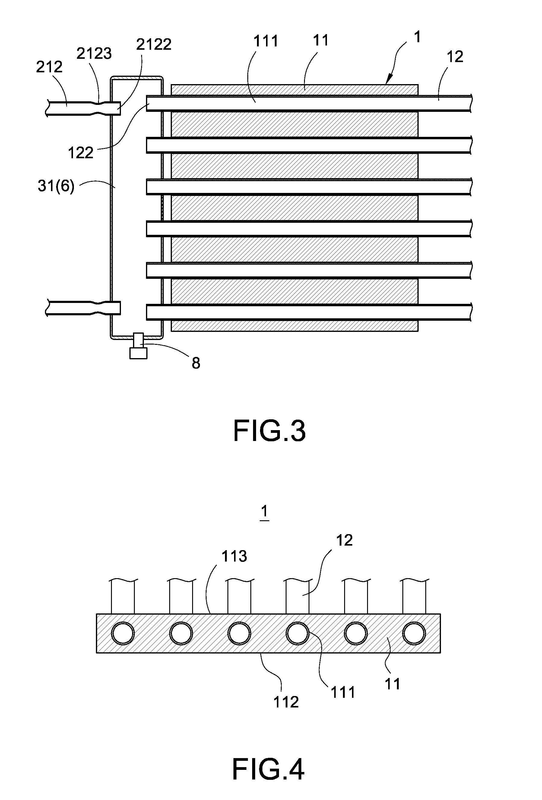
[0031]The evaporator 1 includes a heat conducting element 11 and plurality of evaporation pipes 12, and both ends of each evaporation pipe 12 have a liquid inlet end 122 and a gas outlet end 123 respectively. With reference to FIGS. 1 to 4 for a heat conducting element 11 of the first preferred embodiment of the present invention, the heat conducting element 11 has a plurality of through holes 111, and each evaporation pipe 12 i...


PUM


Abstract

A loop thermosyphon cooling device includes an evaporator, a condenser and a communication assembly. The evaporator includes a heat conducting element and evaporation pipes, and the heat conducting element has through holes, and each evaporation pipe is passed and positioned into each respective through hole. The condenser includes a condensation pipe. The communication assembly includes a first barrel and a second barrel, and both ends of each evaporation pipe are communicated with the first and second barrels, and both ends of the condensation pipe are communicated with the first and second barrels, so that the evaporation pipe, condensation pipe, first barrel and second barrel jointly define a loop. A communication assembly is coupled between the evaporation pipe and the condensation pipe, and the quantity of evaporation pipes and condensation pipes can be increased or decreased as needed, and the thermosyphon cooling device is compact and high heat dissipation efficiency.

Description

FIELD OF THE INVENTION[0001]The present invention relates to a cooling device, and more particularly to the loop thermosyphon cooling device.BACKGROUND OF THE INVENTION[0002]Cooling devices are used extensively in different places such as playgrounds, malls and factories where high bay lamps are installed and used as a main light source, and the light source of the high bay lamp is gradually replaced by low power consuming LEDs. However, LEDs will generate a large amount of heat, so that it is necessary to add a cooling device at the high bay lamp to assist the effect of dissipating the heat generated by the LEDs. In addition, places such as machine rooms having equipment like mainframe computers, servers or instruments installed therein may accumulate lots of heat after a long time of the operation, so that the cooling device is required to prevent the equipment from being damaged and achieve the heat dissipation effect.[0003]A conventional “loop cooling device” as disclosed in Tai...

Claims


Application Information

Patent Timeline
IPC IPC(8): F28D15/02
CPCF28D15/02F28D15/0266F28D15/0275
Inventor LANGE, TORBEN BJERRISGAARDWANG, I-CHING
Owner COOLING HOUSE
Why Eureka
Try Eureka