Adhesive dispensing system and method with melt on demand at point of dispensing

a dispensing system and adhesive technology, applied in the direction of liquid surface applicators, coatings, packaging, etc., can solve the problems of unsatisfactory purging of solid materials from dispensing applicators, non-solidification of adhesives, etc., and achieve the effect of rapid melting of adhesives

Active Publication Date: 2014-05-01
NORDSON CORP
View PDF4 Cites 20 Cited by
  • Summary
  • Abstract
  • Description
  • Claims
  • Application Information

AI Technical Summary

Benefits of technology

[0007]According to one embodiment of the current invention, an adhesive dispensing system is provided for melting adhesive on demand and dispensing the adhesive. The dispensing system includes a dispensing applicator having a manifold with a manifold passage and a dispensing module coupled to the manifold passage. The dispensing system also includes a receiving device positioned proximate to the dispensing applicator. The receiving device includes a receiving chamber for receiving a small amount of solid adhesive at the location of the dispensing applicator. The receiving device also includes an outlet positioned to deliver melted adhesive into the manifold immediately after melting. A first heating device is positioned proximate to the manifold and to the receiving device, and the first heating device rapidly melts the adhesive on demand. A second heating device positioned within the manifold applies heat energy to maintain the adhesive as a liquid in the manifold passage. The operation of the first and second heating devices prevents re-solidification of the melted adhesive.

Problems solved by technology

Consequently, the melted adhesive does not solidify downstream from the first heating device, and purging of solid material from the dispensing applicator is rendered unnecessary.

Method used


Image

  • Adhesive dispensing system and method with melt on demand at point of dispensing
  • Adhesive dispensing system and method with melt on demand at point of dispensing
  • Adhesive dispensing system and method with melt on demand at point of dispensing

Examples


Embodiment Construction

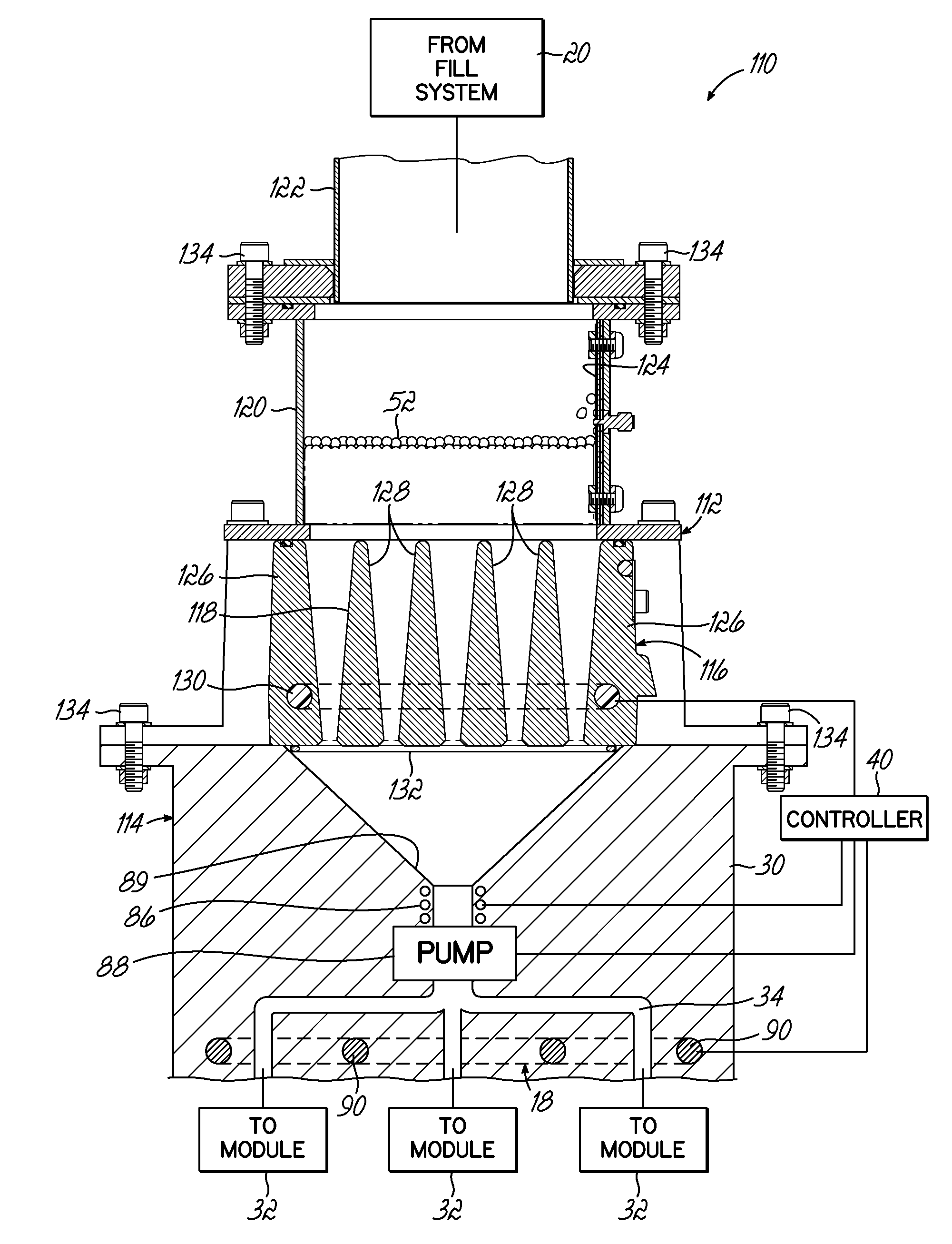
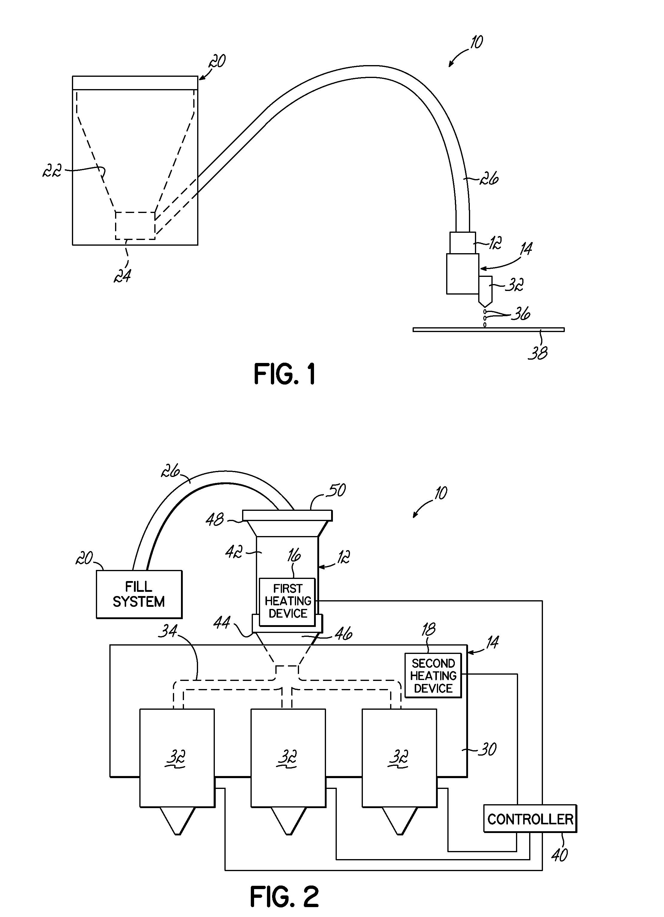
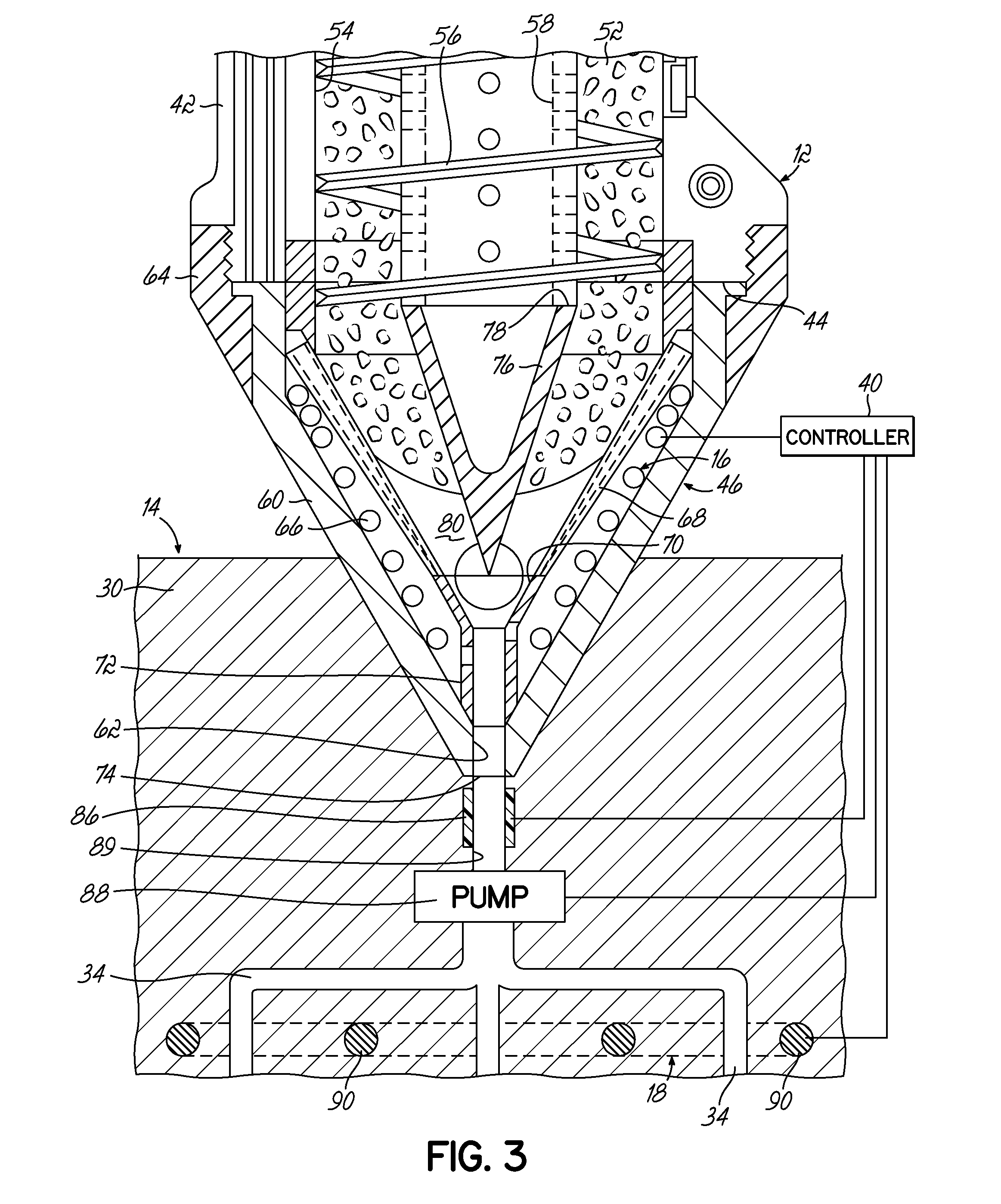
[0020]Referring to FIGS. 1 through 3, an adhesive dispensing system 10 in accordance with one exemplary embodiment of the invention is shown. The adhesive dispensing system 10 is configured to improve the dispensing operation by using a melt on demand process at the point of dispensing to melt solid adhesive material rapidly when that material is needed for dispensing. To this end, the storage of molten hot melt adhesive at elevated temperatures in reservoirs, tanks, and / or heated hoses located remote from the point of dispensing is substantially eliminated from the adhesive dispensing system 10, and the likelihood for degradation and / or charring of the adhesive is reduced significantly as a result. Moreover, the adhesive does not require transport or pumping over lengthy distances between the point of melting and the point of dispensing because the melting occurs at the point of dispensing. In other words, a receiving device 12 of the adhesive dispensing system 10 is located at the...


PUM


Abstract

An adhesive dispensing system and method are configured to melt adhesive on demand and maintain the adhesive in a liquid state between dispensing cycles. The dispensing system includes a dispensing applicator with a manifold passage, a receiving device including a receiving chamber for holding a small amount of solid adhesive at the dispensing applicator and a first heating device for melting the adhesive on demand, and a second heating device at the manifold to maintain the temperature of the melted adhesive before dispensing. The receiving device is positioned adjacent to or partially nested within a manifold of the dispensing applicator such that the melted adhesive is delivered directly into the dispensing applicator. The second heating device applies heat energy to maintain the adhesive in the manifold passage as a liquid.

Description

CROSS-REFERENCE TO RELATED APPLICATION[0001]This application claims the benefit of U.S. Provisional Patent Application Ser. No. 61 / 718,976, filed on Oct. 26, 2012 (pending), the disclosure of which is incorporated by reference herein in its entirety.FIELD OF THE INVENTION[0002]The present invention generally relates to an adhesive dispensing system, and more particularly, to adhesive dispensing systems and methods using a receiving device for melting adhesive at the point of dispensing.BACKGROUND[0003]A conventional system for dispensing heated adhesive (i.e., a hot-melt adhesive dispensing system) generally includes a melter having a tank or reservoir for receiving adhesive materials in solid or liquid form, a heater grid for heating and / or melting the adhesive materials in the tank or reservoir, and a pump in communication with the heater grid and the tank or reservoir for driving and controlling the dispensation of the heated adhesive from the melter to downstream dispensing guns...

Claims


Application Information

Patent Timeline
Patent Type & Authority Applications(United States)
IPC IPC(8): B67D7/80
CPCB05C9/14B05C11/1034B05C11/1042B05C11/1044B05C11/1047
Inventor VARGA, LESLIE J.
Owner NORDSON CORP
Why Eureka
Try Eureka